

Multipole Ring Sensor Magnet, DC Motor Magnetic Ring, Motor Speed Controller Magnetic Ring, Permanent Magnet for Brushless DC Motor, Robot Vacuum Cleaner Magnetic Ring, Garage Door Motor Magnet, Garage Door Actuator Magnet, Brushless Motor Sensor Magnet, DC Motor Magnet, DC Motor Field Magnet
Global door-to-door delivery
Pre-delivery testing ensures accuracy
Best cost- performance value on market
Free, self-service search of CC's magnetic ring mold inventory.
CCmagnetics' core value is to sincerely help every customer, share our mold inventory information for free and transparently, and help customers save time and money in selecting the magnetic rings they need.
Description:
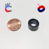
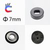
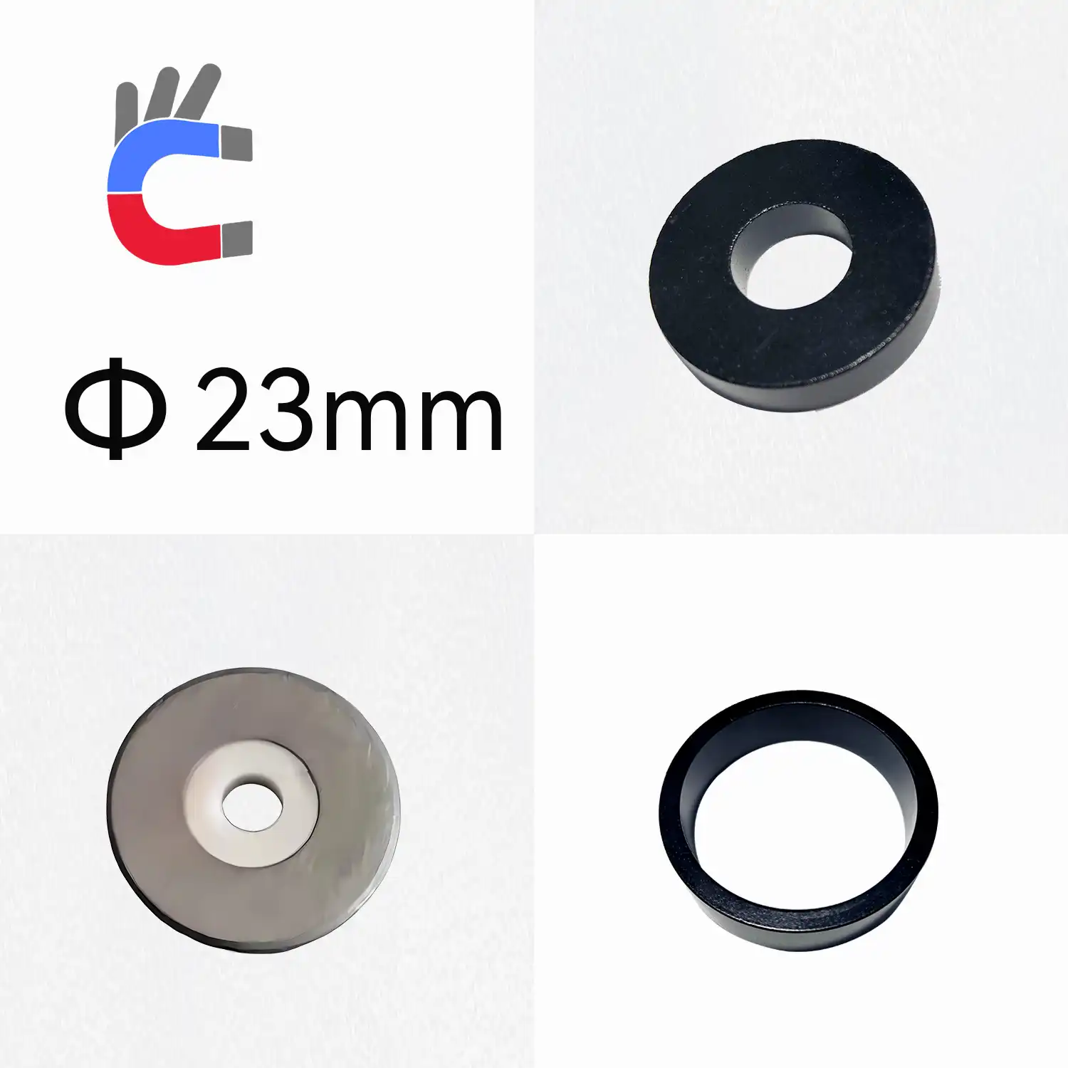
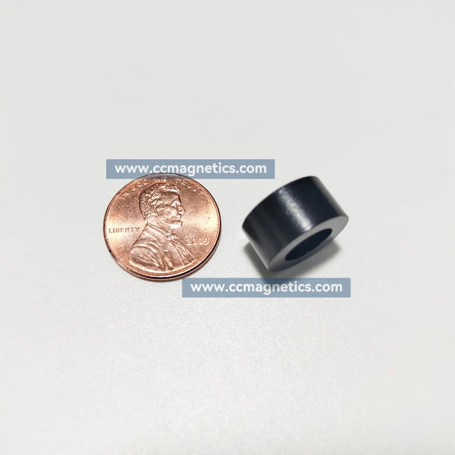
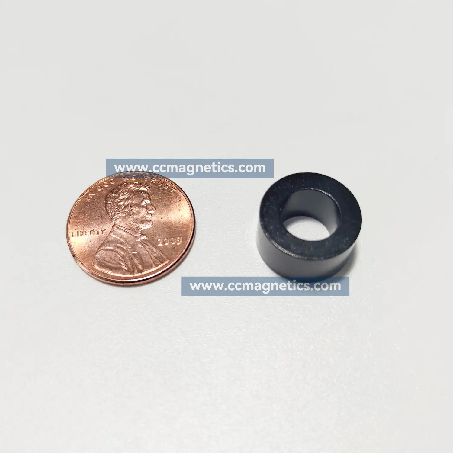
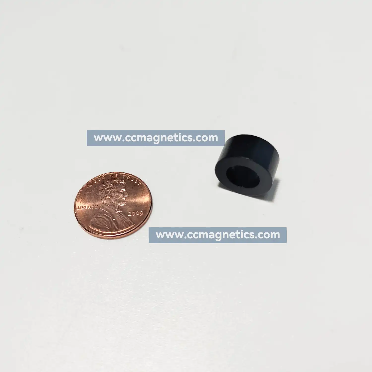
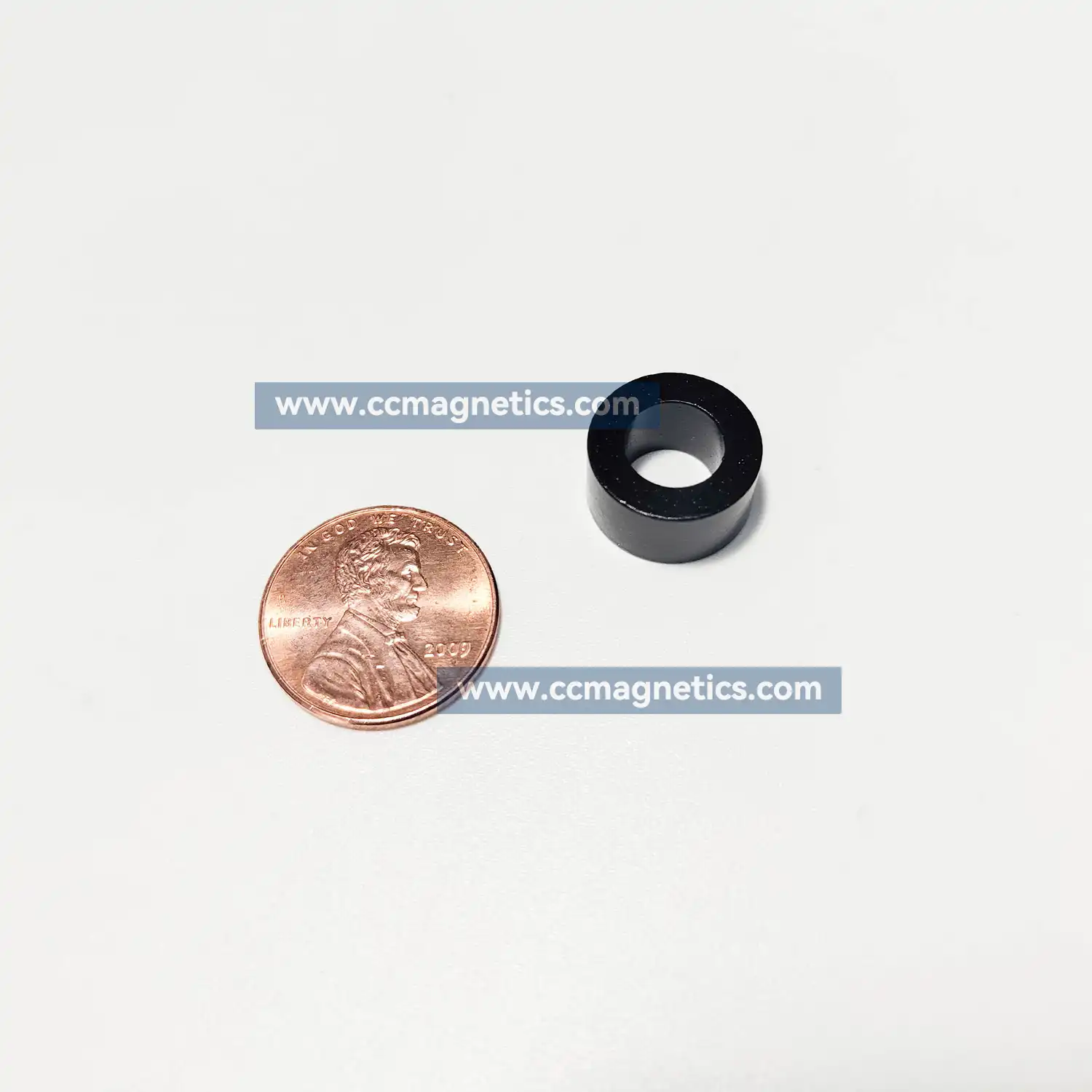
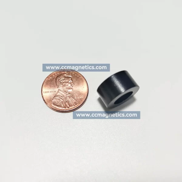
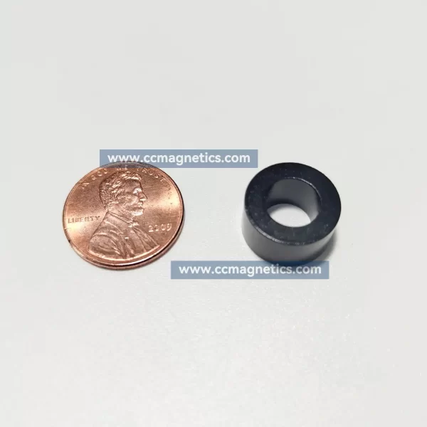
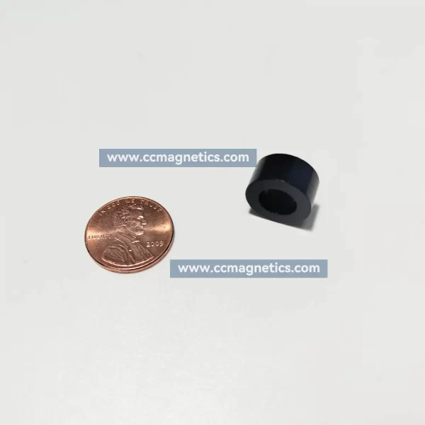
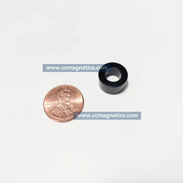
CCmagnetics 23mm outer diameter magnetic rings offer a wide range of options for garage door motors, brushless motors, and DC motors. Manufactured using high-quality ferrite, injection molded ferrite, sintered ferrite, and bonded NdFeB materials, our rings deliver reliable magnetic performance, dimensional accuracy, and excellent temperature stability. With our global delivery network, we can ship your order directly to your door.
Specification:
Magnetization method
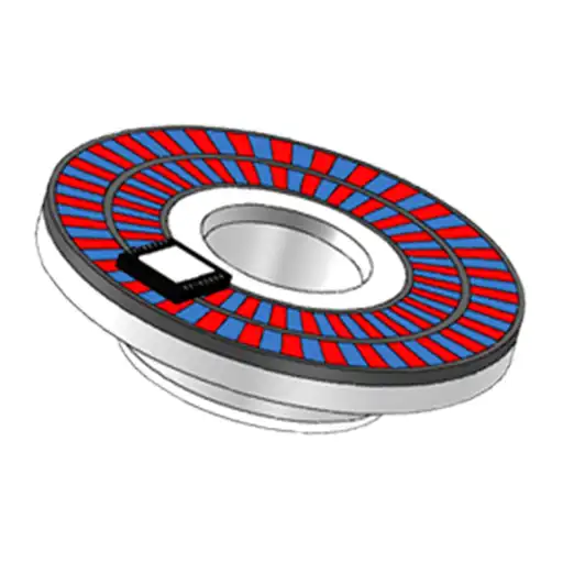
Axial, Rotary
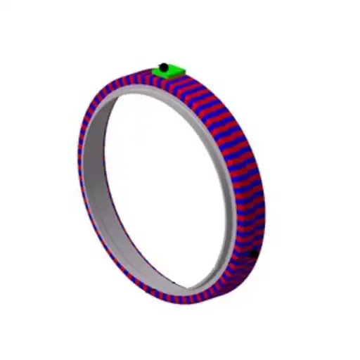
Radial, Rotary
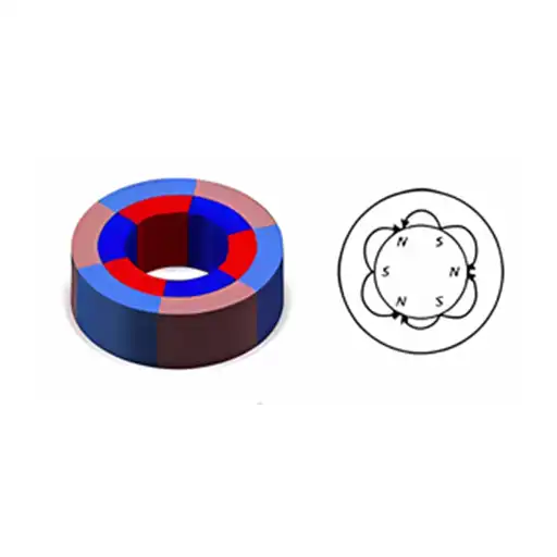
Inter, Radial, Rotary
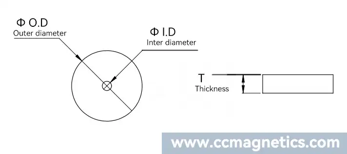
| O.D (mm) |
I.D (mm) |
Thick (mm) |
Pole Qty | Material | Surface magnetic field |
Magnetization method |
|---|---|---|---|---|---|---|
| 23 | 8 | 12P | Ferrite magnets | 90-10mT | Radial, Rotary | |
| 23 | 18 | 4 | 32P | Bonded neodymium magnets | 100-110mT | Radial, Rotary |
| 23 | 15 | 5 | 10P | Bonded neodymium magnets | 160-170mT | Radial, Rotary |
| 23 | 4.95 | 4 | 8P | Ferrite magnets | 90-96mT | Radial, Rotary |
| 23 | 17.5 | 8 | 2P | Injection molded ferrite magnets | 85-95mT | Radial, Rotary |
| 23.6 | 3.9 | 18 | 2P | Ferrite magnets | 175-180mT | Radial, Rotary |
| 23.9 | 6.5 | 9.34 | 6P | Injection molded ferrite magnets | 95-100mT | Axial, Rotary |
Millimeters to inches conversion table
The fraction inches are rounded to 1/64 resolution.
| Millimeters(mm) | Inches(") (decimal) |
Inches(") (fraction) |
|---|---|---|
| 0.01mm | 0.0004″ | 0″ |
| 0.1 mm | 0.0039 ″ | 0 ″ |
| 1 mm | 0.0394 ″ | 3/64 ″ |
| 2 mm | 0.0787 ″ | 5/64 ″ |
| 3 mm | 0.1181 ″ | 1/8 ″ |
| 4 mm | 0.1575 ″ | 5/32 ″ |
| 5 mm | 0.1969 ″ | 13/64 ″ |
| 6 mm | 0.2362 ″ | 15/64 ″ |
| 7 mm | 0.2756 ″ | 9/32 ″ |
| 8 mm | 0.3150 ″ | 5/16 ″ |
| 9 mm | 0.3543 ″ | 23/64 ″ |
| 10 mm | 0.3937 ″ | 25/64 ″ |
| 20 mm | 0.7874 ″ | 25/32 ″ |
| 30 mm | 1.1811 ″ | 1 3/16 ″ |
| 40 mm | 1.5748 ″ | 1 37/64 ″ |
| 50 mm | 1.9685 ″ | 1 31/32 ″ |
| 60 mm | 2.3622 ″ | 2 23/64 ″ |
| 70 mm | 2.7559 ″ | 2 3/4 ″ |
| 80 mm | 3.1496 ″ | 3 5/32 ″ |
| 90 mm | 3.5433 ″ | 3 35/64 ″ |
| 100 mm | 3.9370 ″ | 3 15/16 ″ |
Note:If you require sensor recommendations, please contact our sales representatives and we will provide you with suggestions for pairing them.
m_omenzetter –
quality perfect.
jeannecolavito –
Fantastic service and fantastic products I will go back 100%
jaemosc –
Transaction was super smooth from start to finish and they were at my door so quickly. Super service.