
 Deutsch
 Русский
 Español
 Français
 한국어
한국어 日本語
日本語


Non-Contact Magnetic Drives Models,Magnetic conveyor track,Magnetic pinion components,Rotary magnetic power transmission,Non-friction magnetic transmission gear
Original factory, accept visitors
Free design, technical support
Quality assurance, one year warranty
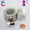
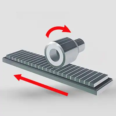
About magnetic rack & pinion gears
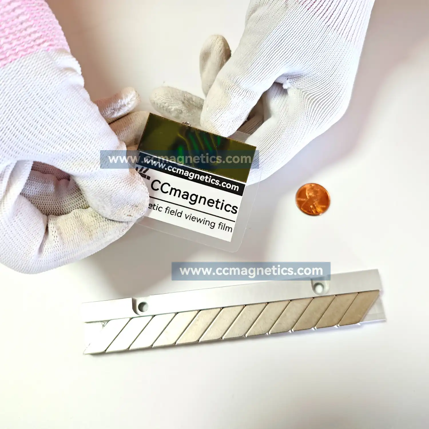
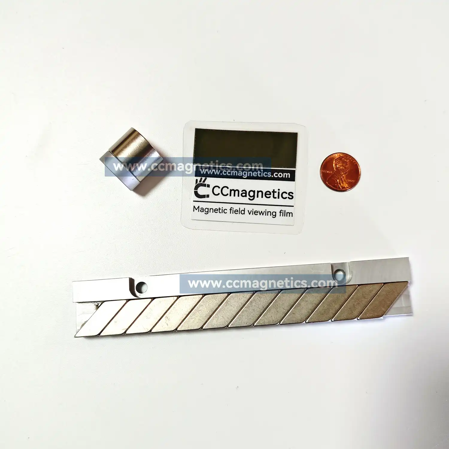
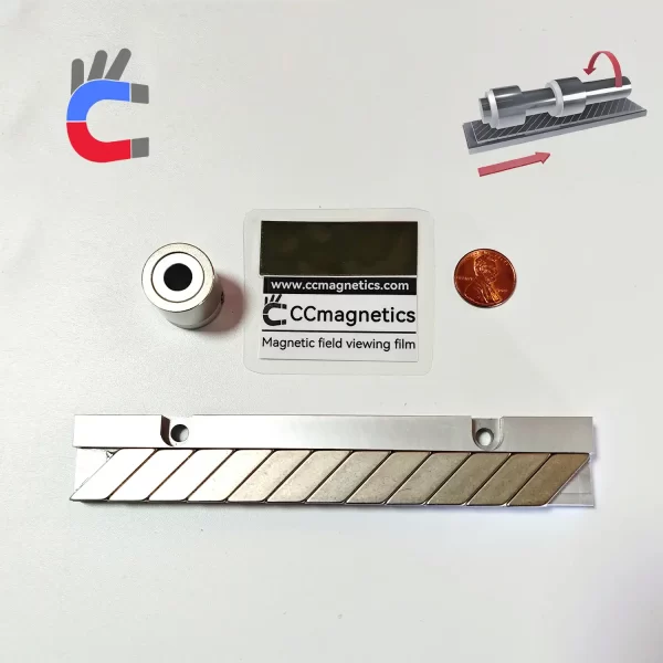
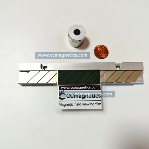
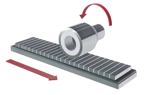
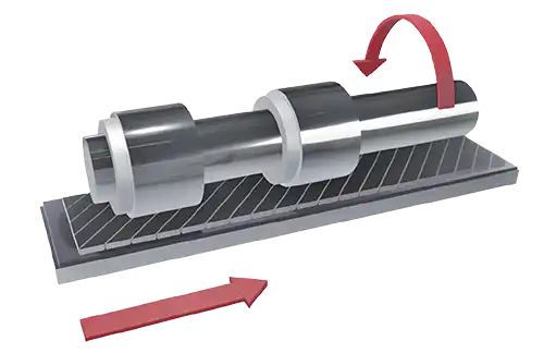
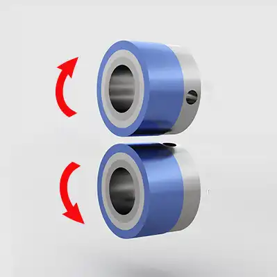
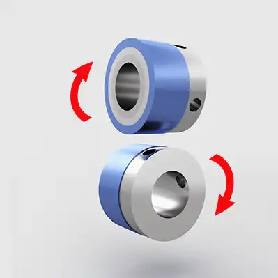
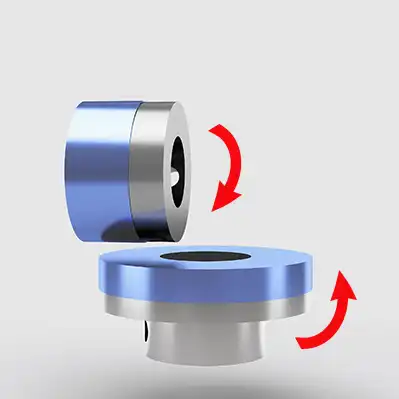
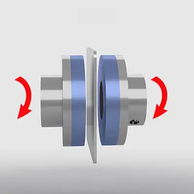
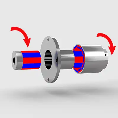
This proposal introduces an unprecedented new type of transportation rack that transforms into a rack simply by being attached. It incorporates a magnetic rack & pinion gear system, which operates on two transmission modes: Parallel and right-angle. Standardly, the system utilizes magnetic gears with an outer diameter of 35mm. However, magnetic gears with larger diameters can be employed as well, tailored to specific customer usage requirements.
 |
 |
|---|---|
| Pros of parallel type | Pros of cross type |
| 1. Stronger | 1. Smooth working process |
| 2. Lower price | 2. Smaller vibration during operation |
| 3. Any shaft diameter can be customized | 3. Any shaft diameter can be customized |
| 4. Any track length can be customized | 4. Any track length can be customized |
| Cons of parallel type | Cons of cross type |
| The vibration during operation is greater than the cross type with the same number of poles. |
The torque during operation is less than the parallel type with the same number of poles. The price is higher because the track poles are tilted. |
Product Parameter
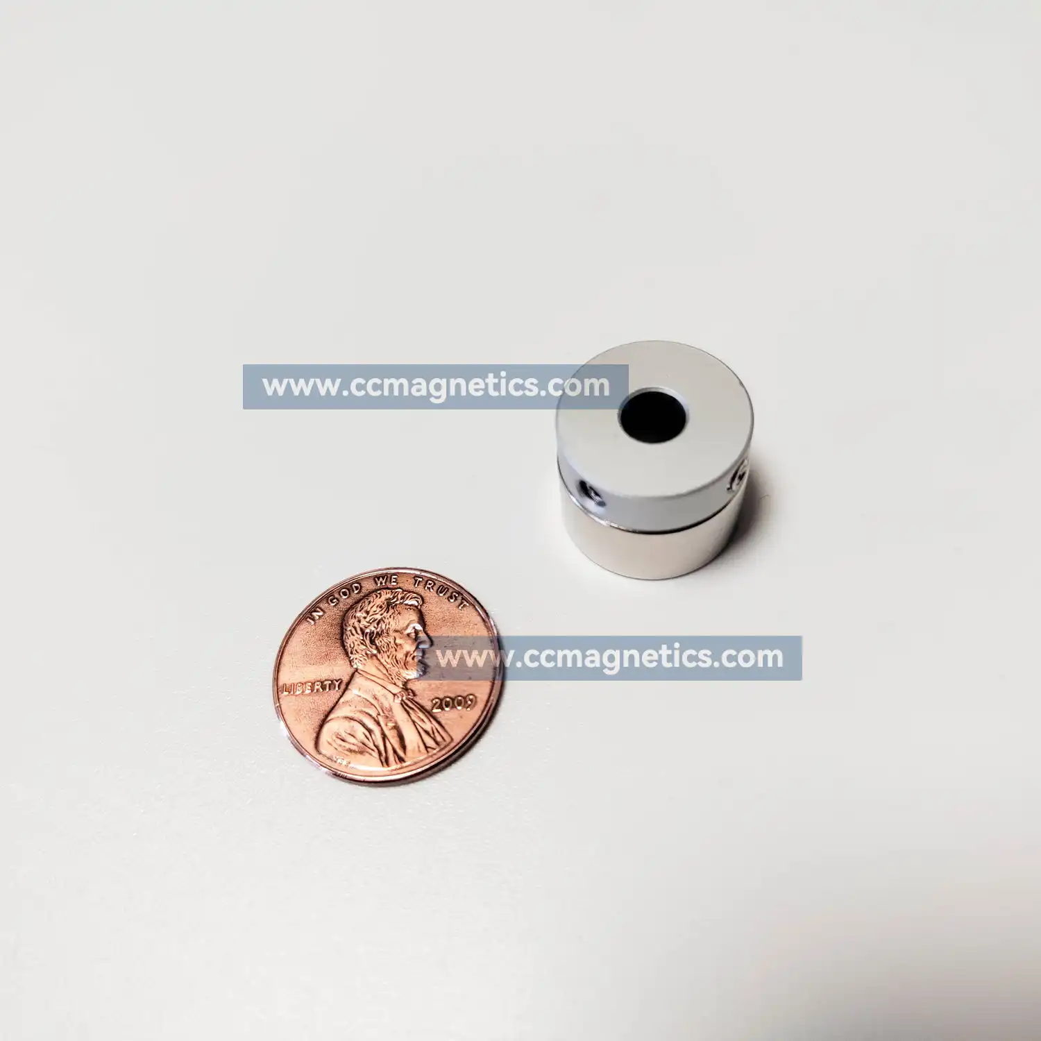
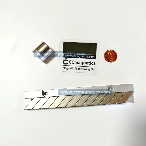
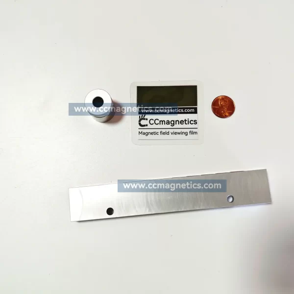
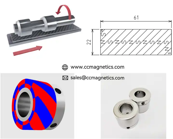
Cross Type: Pinion ( MGS-A ) outer diameters range from 13 mm to 65 mm, with custom shaft diameters. Magnetic track widths can be customized from 8 mm to 35 mm, and track lengths can be customized to any desired length.
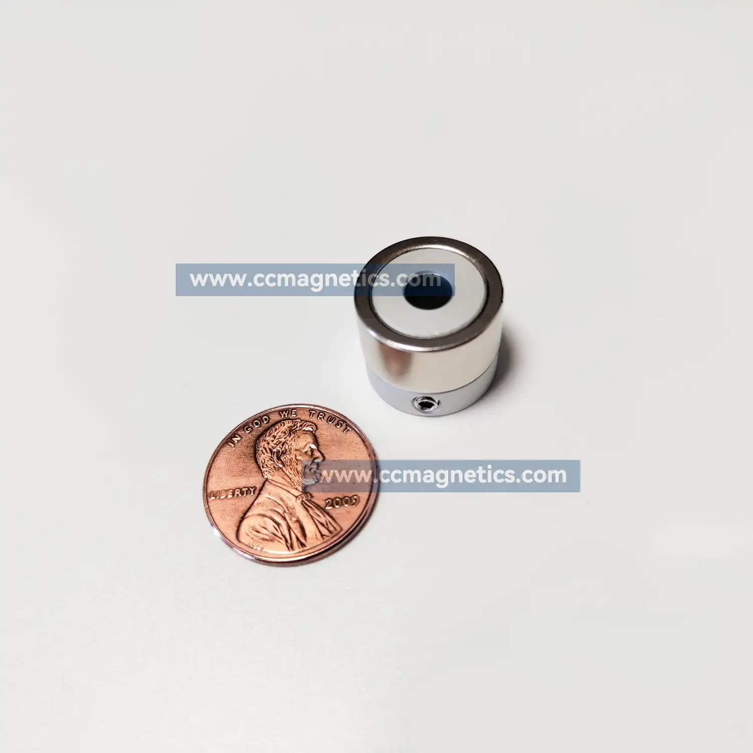
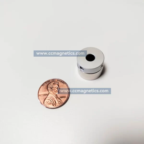
Pinion parameter
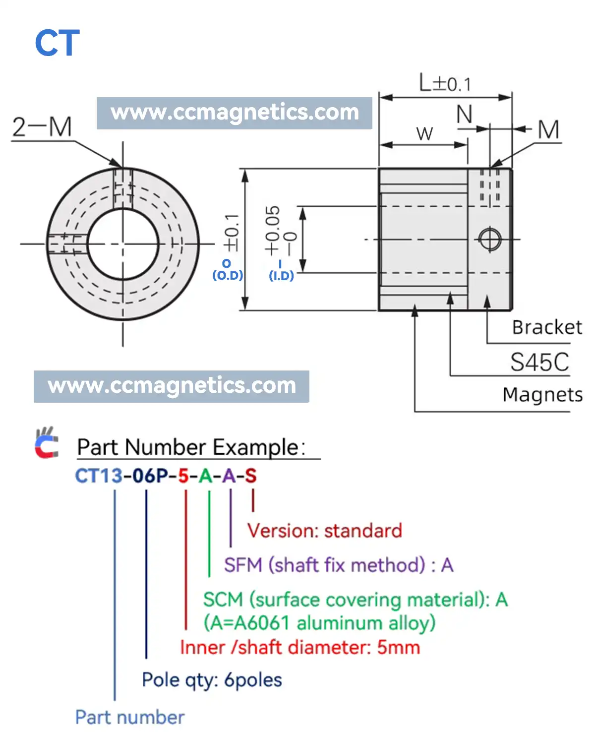
| PN | PQ | (I) I.D | SCM | SFM | MC | Tq | (O) O.D | L | W | F | M |
|---|---|---|---|---|---|---|---|---|---|---|---|
| CT13 | 6P | 5~6 | A/S | A | H | 0.012N.m | 13 | 15 | 10 | 2.5 | M3 |
| CT16 | 8P | 5~8 | A/S | A | H | 0.025N.m | 16 | 13 | 8 | 2.5 | M3 |
| CT16 | 12P | 5~8 | A/S | A | H | 0.015N.m | 16 | 13 | 8 | 2.5 | M3 |
| CT18 | 8P | 6~8 | A/S | A | H | 0.05N.m | 18 | 15 | 10 | 2.5 | M3 |
| CT21 | 6P | 6~12 | A/S | C/A | F/H | 0.13N.m | 21 | 21 | 15 | 3 | M4 |
| CT21 | 8P | 6~12 | A/S | C/A | F/H | 0.11N.m | 21 | 21 | 15 | 3 | M4 |
| CT21 | 16P | 6~12 | A/S | C/A | F/H | 0.07N.m | 21 | 21 | 15 | 3 | M4 |
| CT22 | 8P | 8~12 | L/T | A | F/H | 0.09N.m | 22 | 22 | 16 | - | M4 |
| CT22 | 18P | 6~12 | A/S | C/A | F/H | 0.07N.m | 22 | 18 | 12 | 3 | M4 |
| CT25 | 10P | 6~15 | A/S | C/A | F/H | 0.15N.m | 25 | 22 | 15 | 3.5 | M4 |
| CT26 | 8P | 6~15 | A/S | C/A | F/H | 0.2N.m | 26 | 21 | 14 | 3.5 | M4 |
| CT26 | 10P | 6~15 | A/S | C/A | F/H | 0.16N.m | 26 | 21 | 14 | 3.5 | M4 |
| CT26 | 12P | 6~15 | A/S | C/A | F/H | 0.14N.m | 26 | 21 | 14 | 3.5 | M4 |
| CT26 | 20P | 6~15 | A/S | C/A | F/H | 0.05N.m | 26 | 21 | 14 | 3.5 | M4 |
| CT27 | 8P | 8~12 | L/T | A | F/H | 0.14N.m | 27 | 22 | 15 | - | M4 |
| CT27 | 10P | 8~12 | L/T | A | F/H | 0.11N.m | 27 | 22 | 15 | - | M4 |
| CT28 | 8P | 8~15 | A/S | C/A | F/H | 0.22N.m | 28 | 25 | 17 | 4 | M4 |
| CT29 | 8P | 8~15 | L/T | C/A | F/H | 0.25N.m | 29 | 25 | 17 | 4 | M4 |
| CT30 | 8P | 10~15 | L/T | C/A | F/H | 0.31N.m | 30 | 25 | 18 | 3.5 | M4 |
| CT30 | 10P | 10~15 | L/T | C/A | F/H | 0.28N.m | 30 | 25 | 18 | 3.5 | M4 |
| CT31 | 8P | 10~20 | L/T | A | F/H | 0.25N.m | 31 | 25 | 18 | - | M4 |
| CT31 | 10P | 10~20 | L/T | A | F/H | 0.23N.m | 31 | 25 | 18 | - | M4 |
| CT32 | 08P | 8~20 | A/S | C/A | F/H | 0.4N.m | 32 | 30 | 20 | 5 | M4 |
| CT32 | 10P | 8~20 | A/S | C/A | F/H | 0.32N.m | 32 | 30 | 20 | 5 | M4 |
| CT32 | 12P | 8~20 | A/S | C/A | F/H | 0.28N.m | 32 | 30 | 20 | 5 | M4 |
| CT32 | 20P | 8~20 | A/S | C/A | F/H | 0.09N.m | 32 | 30 | 20 | 5 | M4 |
| CT35 | 08P | 8~20 | A/S | C/A | F/H | 0.55N.m | 35 | 32 | 21.5 | 5.25 | M5 |
| CT35 | 10P | 8~20 | A/S | C/A | F/H | 0.45N.m | 35 | 32 | 21.5 | 5.25 | M5 |
| CT35 | 12P | 8~20 | A/S | C/A | F/H | 0.36N.m | 35 | 32 | 21.5 | 5.25 | M5 |
| CT35 | 18P | 8~20 | A/S | C/A | F/H | 0.36N.m | 35 | 32 | 21.5 | 5.25 | M5 |
| CT36 | 08P | 10~20 | L/T | A | F/H | 0.4N.m | 36 | 32 | 22 | - | M5 |
| CT36 | 10P | 10~20 | L/T | A | F/H | 0.35N.m | 36 | 32 | 22 | - | M5 |
| CT36 | 12P | 10~20 | L/T | A | F/H | 0.3N.m | 36 | 32 | 22 | - | M5 |
| CT39 | 08P | 15~20 | A/S | C/A | F/H | 0.8N.m | 39 | 35.8 | 26.6 | 4.6 | M5 |
| CT39 | 12P | 15~20 | A/S | C/A | F/H | 0.58N.m | 39 | 35.8 | 26.6 | 4.6 | M5 |
| CT39 | 16P | 15~20 | A/S | C/A | F/H | 0.4N.m | 39 | 35.8 | 26.6 | 4.6 | M5 |
| CT40 | 12P | 10-20 | L/T | A | F/H | 0.58N.m | 40 | 36.5 | 26 | - | M5 |
| CT40 | 16P | 15~25 | A/S | C/A | F/H | 0.42N.m | 40 | 34 | 24 | 5 | M5 |
| CT42 | 12P | 15~25 | A/S | C/A | F/H | 0.74N.m | 42 | 30 | 21 | 4.5 | M5 |
| CT42 | 18P | 15~25 | A/S | C/A | F/H | 0.42N.m | 42 | 30 | 21 | 4.5 | M5 |
| CT45 | 10P | 15~30 | A/S | C/A | F/H | 1.2N.m | 45 | 35 | 25 | 4.5 | M4 |
| CT45 | 12P | 15~30 | A/S | C/A | F/H | 0.95N.m | 45 | 35 | 25 | 4.5 | M4 |
| CT46 | 10P | 15-25 | L/T | A | F/H | 0.83N.m | 46 | 27 | 26 | - | M5 |
| CT52 | 10P | 20~35 | A/S | C/A | F/H | 1.45N.m | 52 | 37 | 25 | 5 | M5 |
| CT53 | 10P | 20~30 | L/T | A | F/H | 0.95N.m | 53 | 37 | 26 | - | M5 |
| CT65 | 18P | 20~40 | A/S | C/A | F/H | 1.95N.m | 65 | 50 | 35 | 7.5 | M6 |
| No. | Item | Description | Notes |
|---|---|---|---|
| 1 | PN | Part Number | The number after PN is the outer diameter of the magnetic coupling in millimeters. |
| 2 | PQ | Pole Quantity | Number of magnets on one magnetic coupling. |
| 3 | I | Inner Diameter | Unit of length is millimeters. |
| 4 | SCM | Surface Covering Material | A=A6061 (aluminum alloy), S=SUS304 (stainless steel), L=SUS316L (stainless steel), T=TC4 (Titanium Alloy). |
| 5 | SFM | Shaft Fixing Method | Type A: Setscrew Type B: Setscrew and keyway Type C: Clamping hub slot and keyway. Refer to the drawing for the shaft fixing method. |
| 6 | MC | Metal Casing Coverage | F= Fully H= Half |
| 7 | Tq | Torque | The torque value shown is for a 1mm gap. |
| 8 | O | Outer diameter. | Unit of length is millimeters. |
| 9 | L,W,F,M | Unit of length on the drawing. | Unit of length is millimeters. |
Shaft fixing method
Type A
Setscrew
Type B
Setscrew and keyway
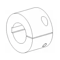
Type C
Clamping hub
slot and keyway
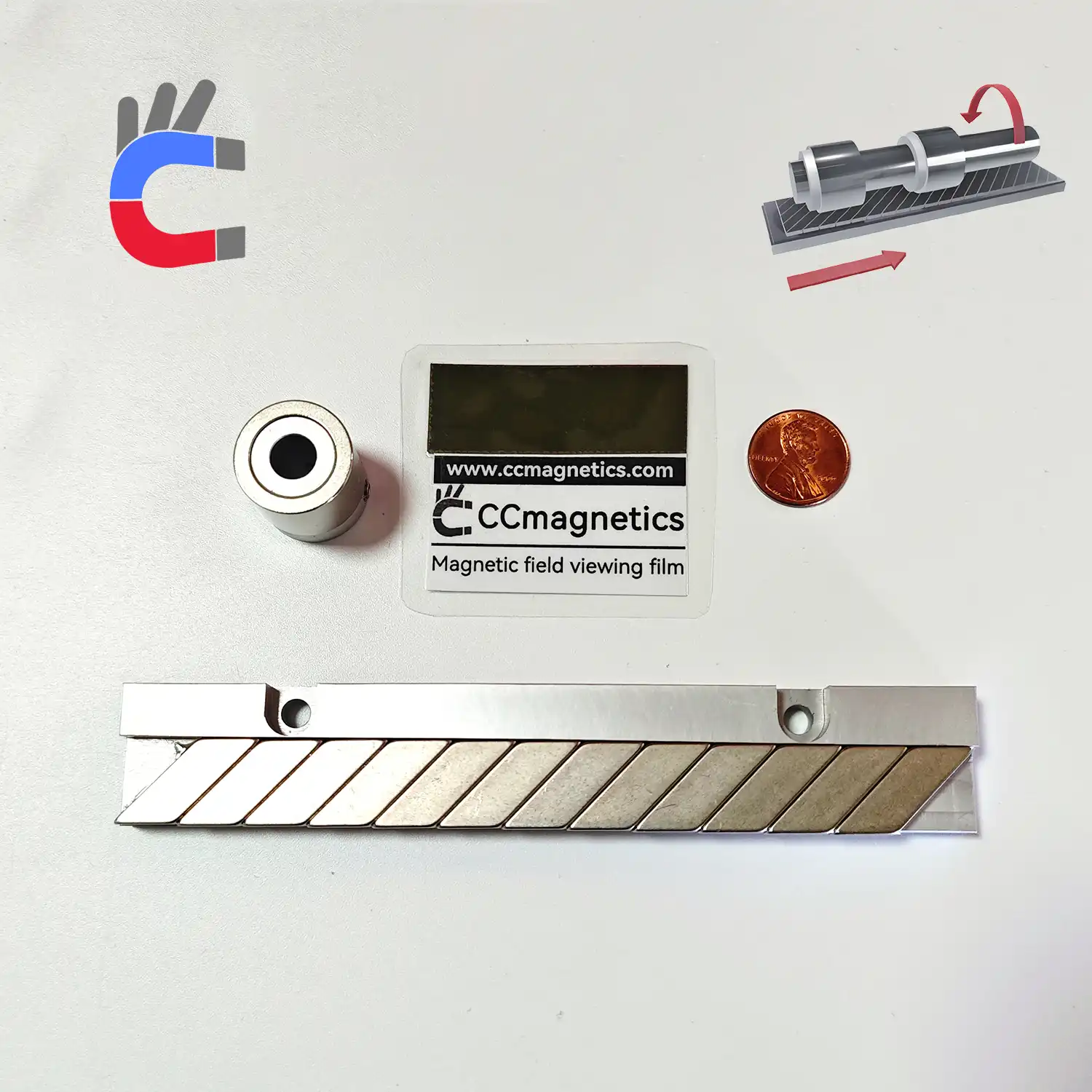
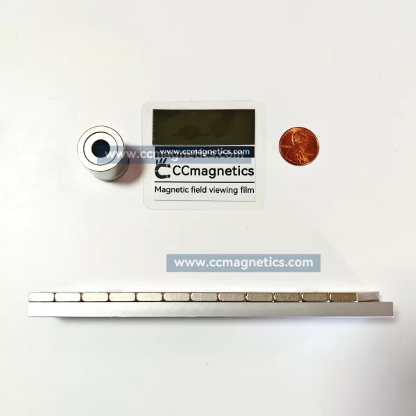
Magnetic track parameter
| Magnetictrack width | Aswide as the magnet part of the pinion gear. |
|---|---|
| Magnetictrack lenth | Customizable |
| Material | Neodymiumsintered magnet / 6061 aluminium alloy |
| Surfacetreatment | Ni-Cu-Ni( Magnets ) |
| Max.operatingtemperature | 80°C |
Note:
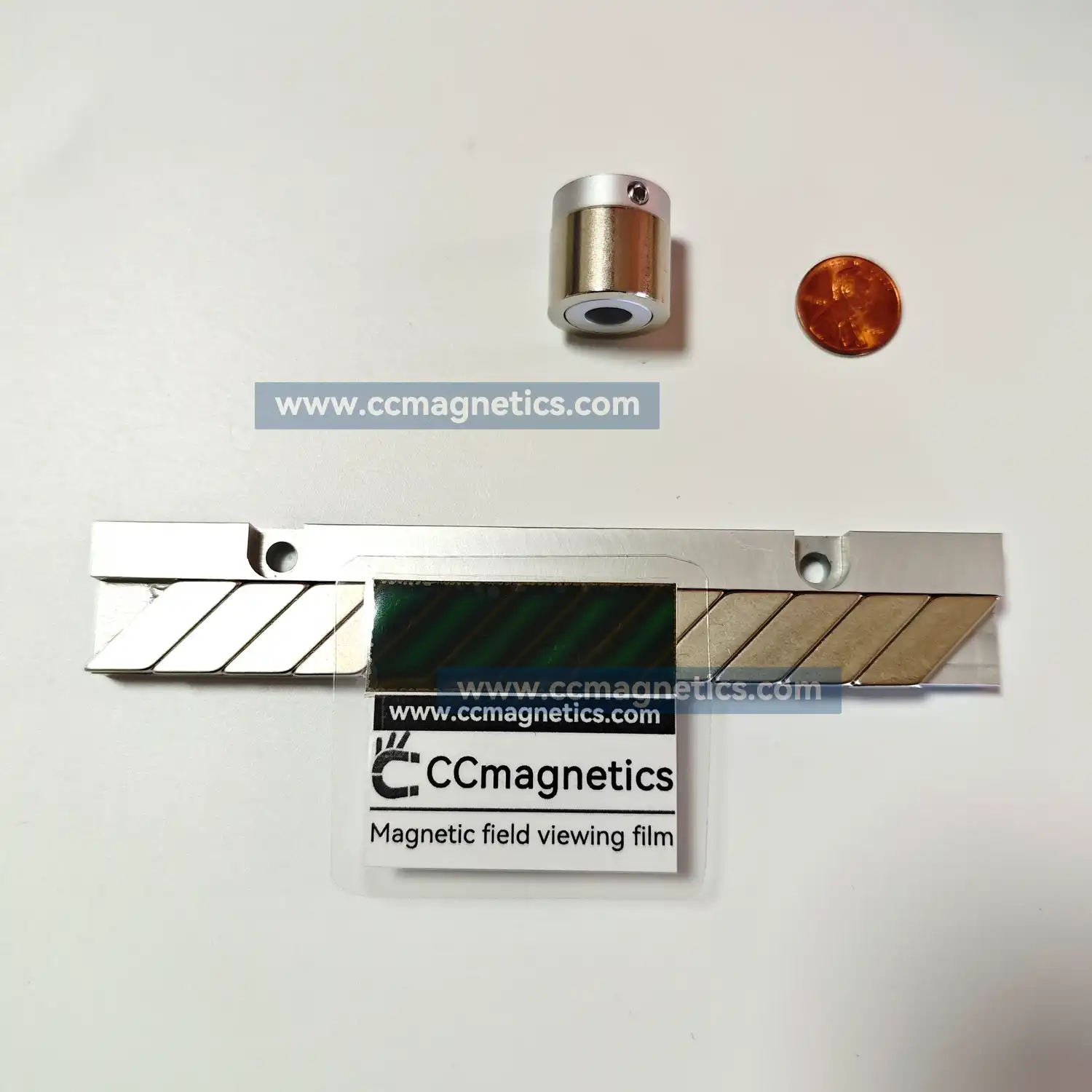
- When there are few magnetic poles, the torque becomes larger. The disadvantage is that the transmission stability is poor and there is shaking during transmission;
- When there are many magnetic poles, the stability is good, but the transmission torque will become smaller. Mixing of medicines and chemicals is suitable for magnetic gear with multiple magnetic poles.
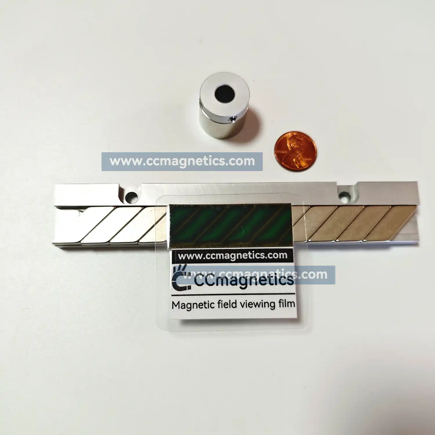
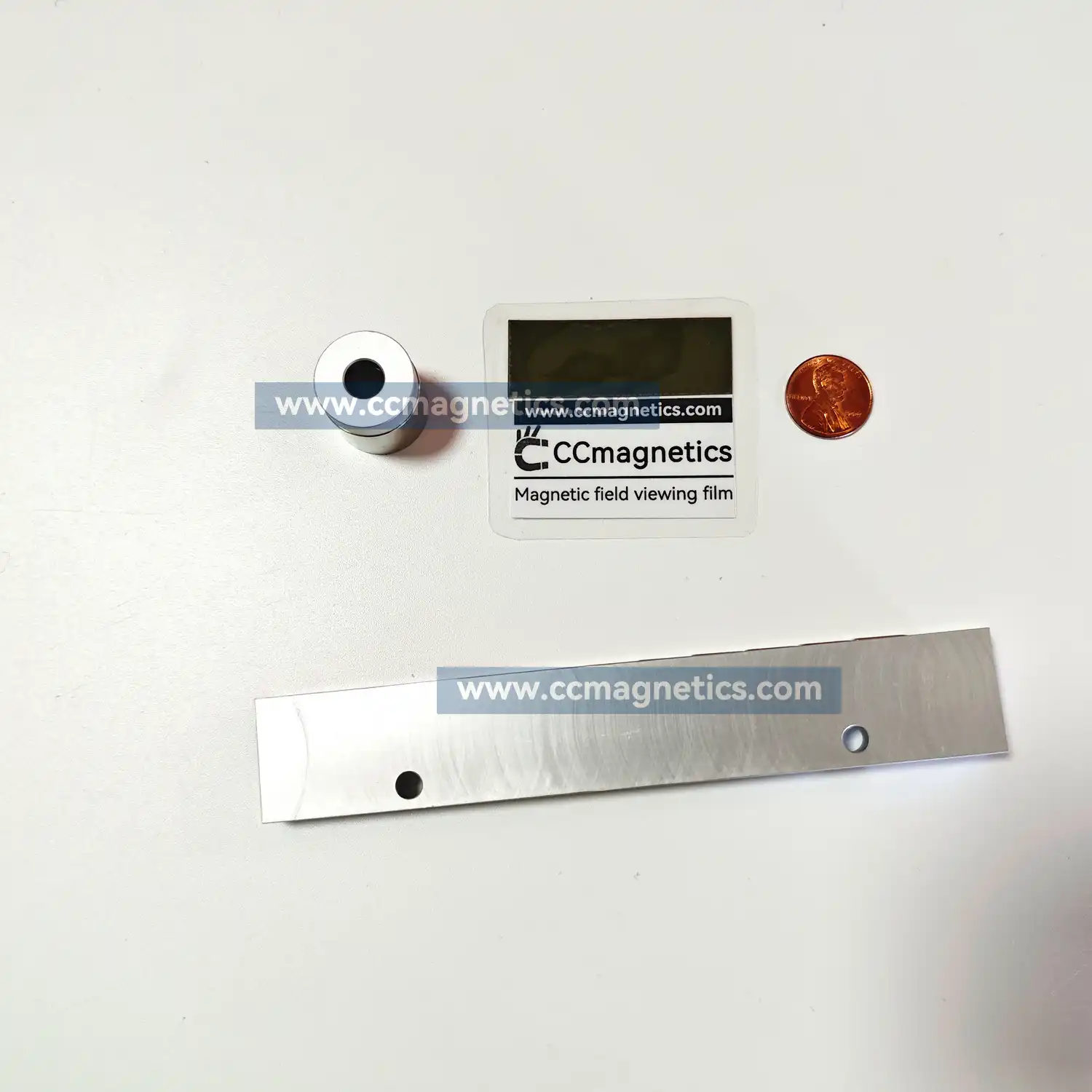
- It is easy to connect and remove racks, and you can change the length according to your imagination.
- Since it is non-contact, no lubricating oil or grease is required.
- The rack mount base can be provided by the customer or customized by us.
- Please contact us for the rack base material, surface treatment, and magnet installation method.
steve –
Mr Magnets were great however , courier company let you down by leaving our magnets outside an office which had nothing to do with us on the same level one , if he looked over to the right as he came up the stairs our office is well marked , luckily we went looking for the magnets after receiving an email to say magnets had been delivered,not good.