
 Deutsch
 Русский
 Español
 Français
 한국어
한국어 日本語
日本語


Original factory, accept visitors
Free design, technical support
Quality assurance, one year warranty
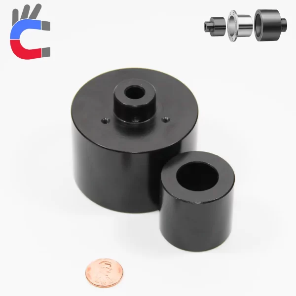
What is magnetic coupler ?
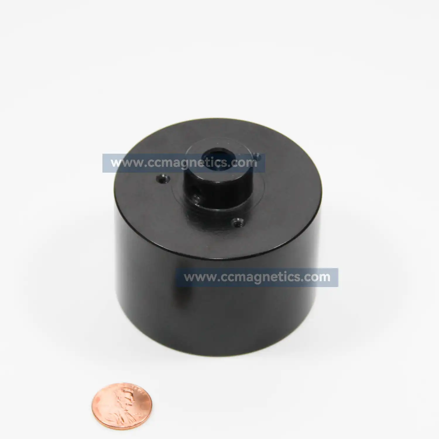
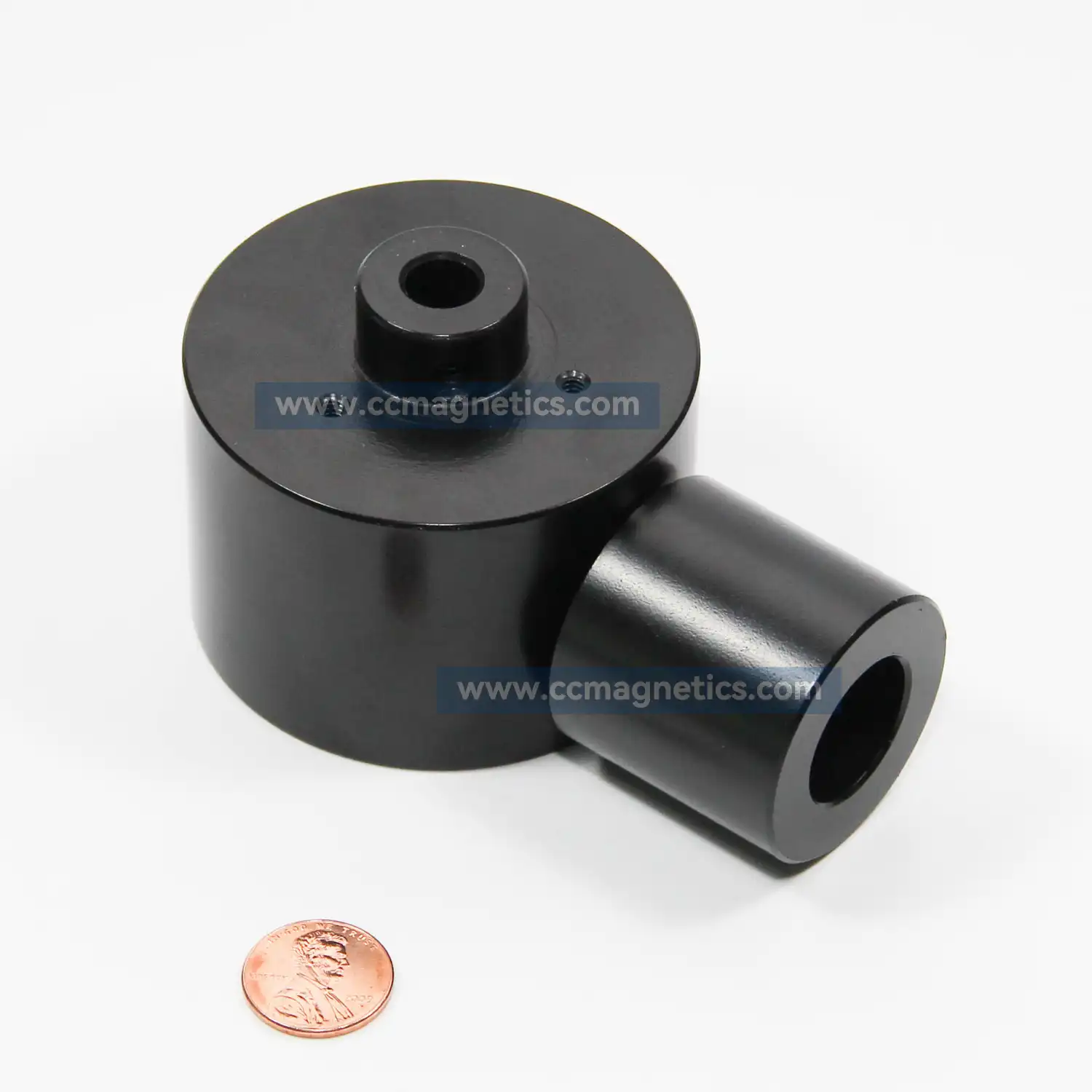
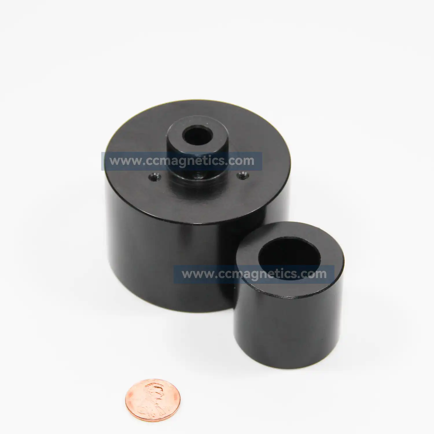
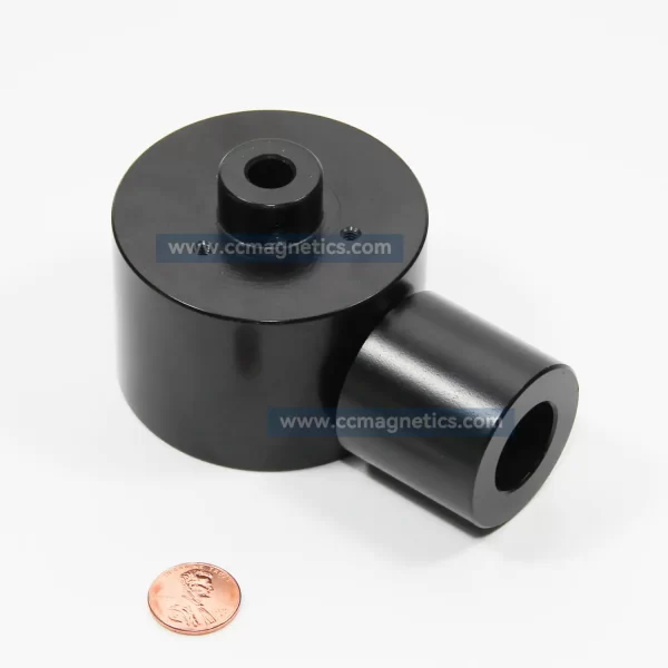
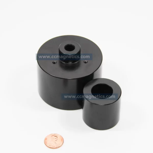
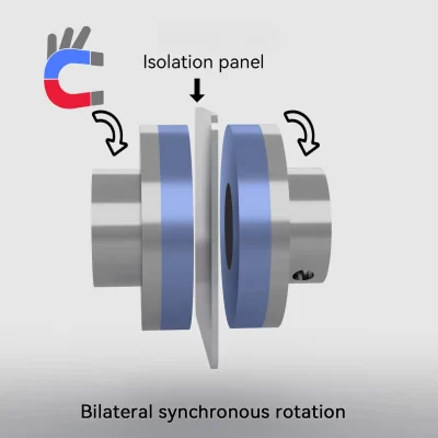
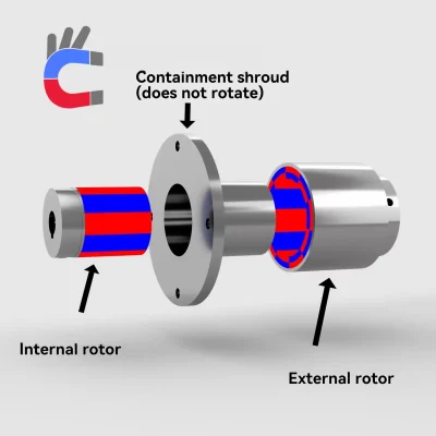
The magnetic coupler transmit the torque without contact through magnetic forces between the internal and external rotor. They ensure hermetic separation between driving and driven side in pumps and agitators sealing hazardous liquids and gases reliably.
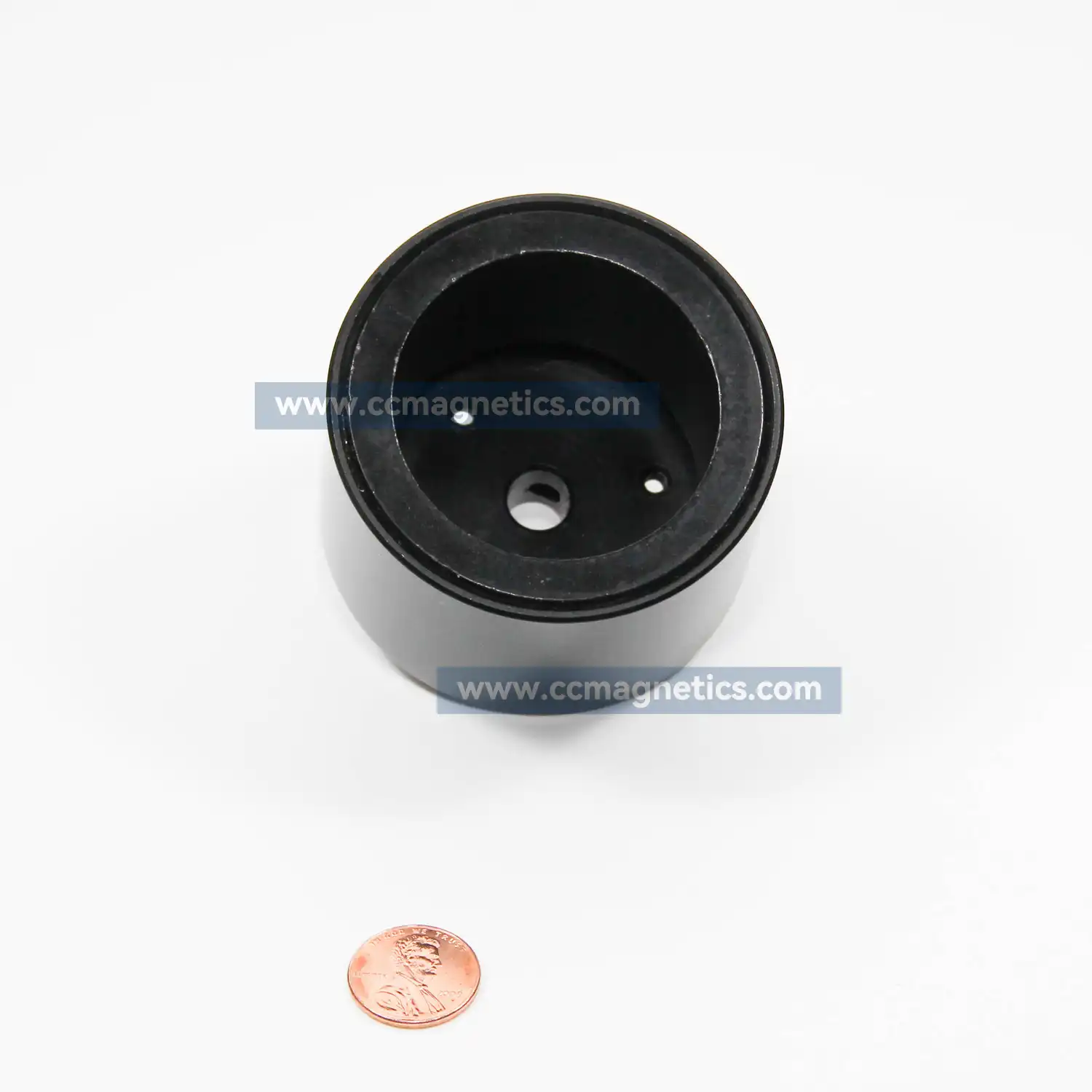
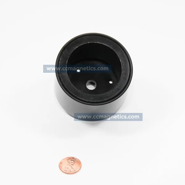
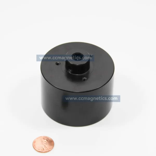
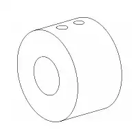
The magnetic coupler consists of an external and an internal rotor. The external rotor has got high-quality, permanent magnets of changing polarity on the inner side while the internal rotor has got them on the outside.The external rotor is usually fixed on the drive side and the magnets are glued in the keyways. The magnets of the internal rotor on the driven side are fully encapsulated.
How magnetic coupler work?
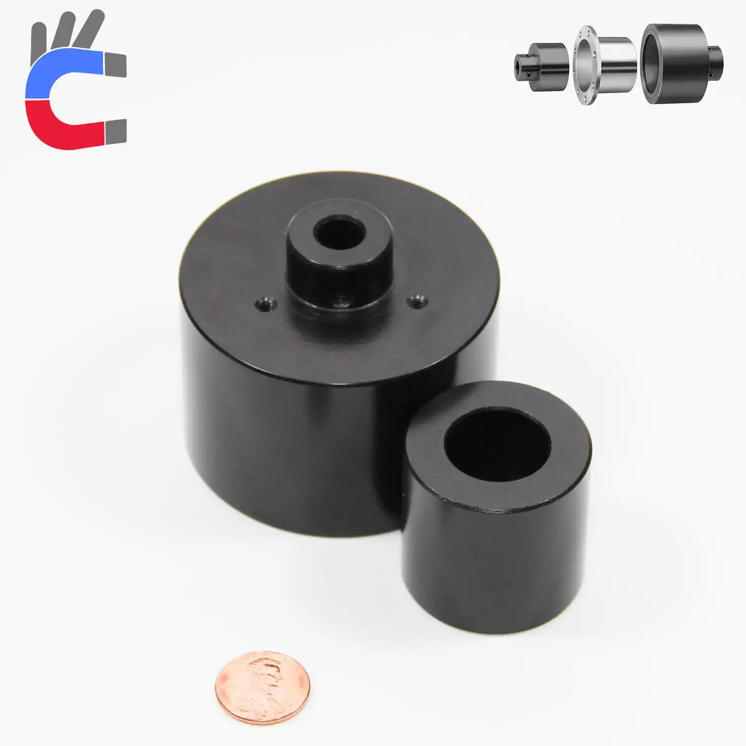
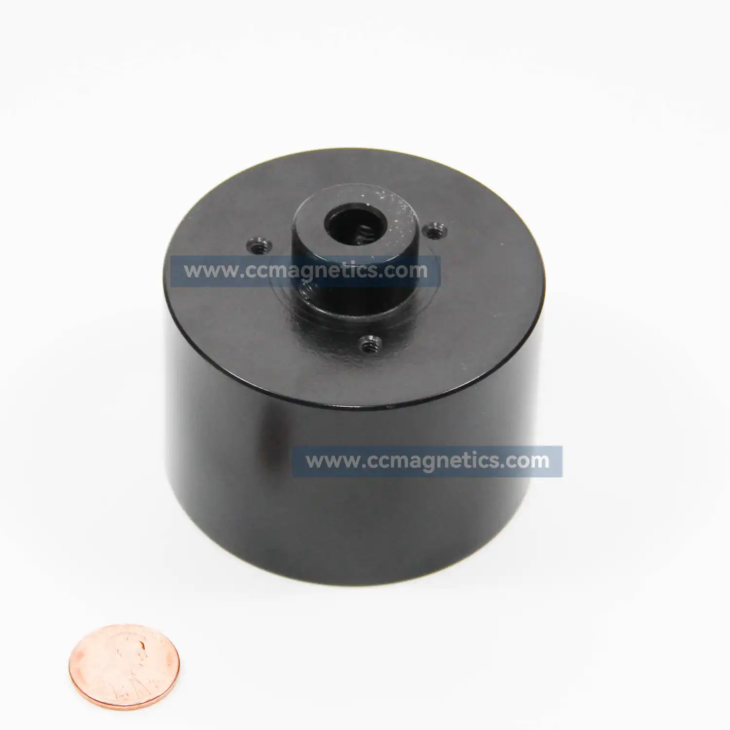
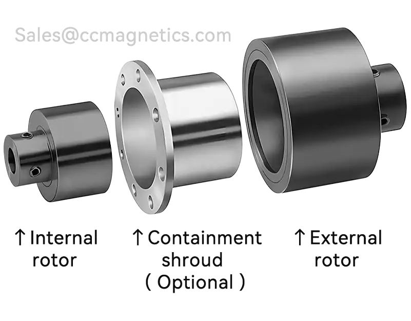
The magnetic coupler consists of three parts. The external rotor consists of a series of rare earth magnets that are ground, potted and attached to the inside diameter of a steel hub. The Internal rotor consists of a series of rare earth magnets that are ground, potted and attached to the outside diameter of a steel rotor. The sealing is achieved statically.
Then there is a synchronous operation under a constant torsion angle. If the maximum coupling torque and the maximum torsion angle are exceeded, the power transmission is interrupted.Since the torque transmission of the magnetic coupler is interrupted, the motor will be effectively protected.The motor will not burn out due to absolute torque transmission.
Application of magnetic coupler
Typical applications: Gear pumps, centrifugal pumps, screw spindle pumps, agitators, PU foaming lines.
The magnetic coupler parameter
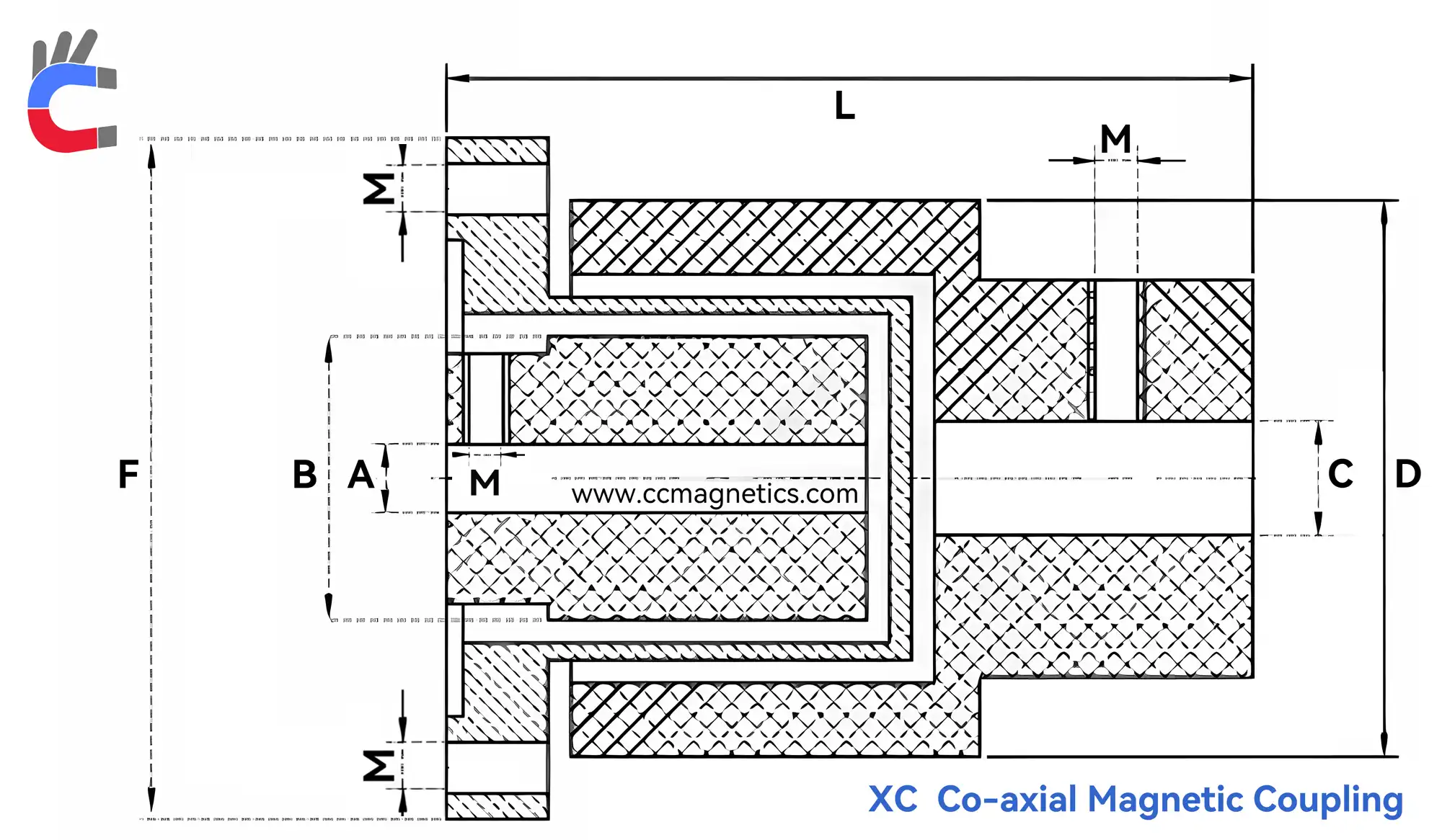
Drawing Parameter Definitions
Unit of Measurement: Millimeters (mm)
Tolerance: ±0.05 mm
Note: The drawing provided here is a simplified version intended for quick reference and comparison only. For detailed engineering specifications, please click the blue button at the top of the page to download the official product manual.
Symbols:
- IB = Internal Bore
- ID = Internal Diameter
- EB = External Bore
- ED = External Diameter
- CD = Containment Shroud Outer Diameter
- M = Metric Screw Thread (e.g., M3 denotes a metric screw with a nominal diameter of 3mm)
- EXM = External rotor mounting hole specification (e.g., 4-M5 denotes 4 mounting holes for M5 screws)
| Model | ΦIB (mm) | ID (mm) | L (mm) | ΦEB (mm) | ED (mm) | M | CD (mm) | Torq. [N.m] |
|---|---|---|---|---|---|---|---|---|
| XC40 | 5~10 | 24 | 58.5 | 8~16 | 40 | M3 | 59.5 | 2.6 |
| XC50 | 8~12 | 30 | 68 | 10~20 | 50 | M4 | 73.5 | 5.8 |
| XC60 | 10~16 | 39 | 87.5 | 10~20 | 60 | M5 | 81.5 | 14.4 |
| XC70 | 12~18 | 44 | 98 | 12~25 | 70 | M6 | 97 | 26 |
| XC80 | 14-20 | 54 | 112 | 15~30 | 80 | M6 | 110 | 48 |
| XC90 | 14-20 | 61 | 120.2 | 16~38 | 90 | M6 | 128 | 67 |
| XC100 | 16-22 | 65 | 138.5 | 20~42 | 100 | M8 | 136 | 92 |
| XC120 | 20~35 | 83 | 156 | 28~56 | 120 | M8 | 165 | 145 |
| XC150 | 30~48 | 107 | 204.5 | 35~75 | 150 | M10 | 201 | 285 |
| XC180 | 38~65 | 134 | 244.5 | 40~95 | 180 | M12 | 233 | 475 |
| XC200 | 38-75 | 146 | 278 | 50~110 | 200 | M12 | 263 | 609 |
| XC232-430 | 38~90 | 130 | 180 | Upon Request | 232 | M16/M6 | 278 | 430 |
| XC232-550 | 38~90 | 130 | 180 | Upon Request | 232 | M16/M6 | 278 | 550 |
| XC287-670 | 38~90 | 165 | 183 | Upon Request | 287 | M16/M6 | 315 | 670 |
| XC287-820 | 38~90 | 165 | 183 | Upon Request | 287 | M16/M6 | 315 | 820 |
| XC287-1000 | 38~90 | 165 | 183 | Upon Request | 287 | M16/M6 | 315 | 1,000 |
| XC298-1260 | 65~95 | 246 | 277 | Upon Request | 298.5 | M10/G1 | 345 | 1,260 |
| XC298-1580 | 65~95 | 246 | 277 | Upon Request | 298.5 | M10/G1 | 345 | 1,580 |
| Model | ΦIB (in) | ID (in) | L (in) | ΦEB (in) | ED (in) | M | CD (in) | Torq. [in·lbs] |
|---|---|---|---|---|---|---|---|---|
| XC40 | 0.2~0.4 | 0.9 | 2.3 | 0.3~0.6 | 1.6 | M3 | 2.3 | 23 |
| XC50 | 0.3~0.5 | 1.2 | 2.7 | 0.4~0.8 | 2 | M4 | 2.9 | 51.3 |
| XC60 | 0.4~0.6 | 1.5 | 3.4 | 0.4~0.8 | 2.4 | M5 | 3.2 | 127.5 |
| XC70 | 0.5~0.7 | 1.7 | 3.9 | 0.5~1.0 | 2.8 | M6 | 3.8 | 230.1 |
| XC80 | 0.6~0.8 | 2.1 | 4.4 | 0.6~1.2 | 3.1 | M6 | 4.3 | 424.8 |
| XC90 | 0.6~0.8 | 2.4 | 4.7 | 0.6~1.5 | 3.5 | M6 | 5 | 593 |
| XC100 | 0.6~0.9 | 2.6 | 5.5 | 0.8~1.7 | 3.9 | M8 | 5.4 | 814.3 |
| XC120 | 0.8~1.4 | 3.3 | 6.1 | 1.1~2.2 | 4.7 | M8 | 6.5 | 1283.4 |
| XC150 | 1.2~1.9 | 4.2 | 8.1 | 1.4~3.0 | 5.9 | M10 | 7.9 | 2522.5 |
| XC180 | 1.5~2.6 | 5.3 | 9.6 | 1.6~3.7 | 7.1 | M12 | 9.2 | 4204.1 |
| XC200 | 1.5~3.0 | 5.7 | 10.9 | 2.0~4.3 | 7.9 | M12 | 10.4 | 5390.1 |
| XC232-430 | 1.5~3.5 | 5.1 | 7.1 | Upon Request | 9.1 | M16/M6 | 10.9 | 3805.8 |
| XC232-550 | 1.5~3.5 | 5.1 | 7.1 | Upon Request | 9.1 | M16/M6 | 10.9 | 4867.9 |
| XC287-670 | 1.5~3.5 | 6.5 | 7.2 | Upon Request | 11.3 | M16/M6 | 12.4 | 5930 |
| XC287-820 | 1.5~3.5 | 6.5 | 7.2 | Upon Request | 11.3 | M16/M6 | 12.4 | 7257.6 |
| XC287-1000 | 1.5~3.5 | 6.5 | 7.2 | Upon Request | 11.3 | M16/M6 | 12.4 | 8,851 |
| XC298-1260 | 2.6~3.7 | 9.7 | 10.9 | Upon Request | 11.8 | M10/G1 | 13.6 | 11,152 |
| XC298-1580 | 2.6~3.7 | 9.7 | 10.9 | Upon Request | 11.8 | M10/G1 | 13.6 | 13,984 |
PART NUMBER CONFIGURATOR
Example: XC40-I6-E8-NS-80-SF
 XC40  -  I6  -  E8  -  NS  -  80  -  SF
   |       |     |      |      |       |
 Model    IB    EB   Shroud  Temp.  Material
- XC40: Magnetic coupling model designation (External rotor outer diameter ED = 40mm).
- I6: Internal rotor shaft bore (IB) = 6mm.
- E8: External rotor drive bore (EB) = 8mm.
- NS: Isolation containment shroud configuration code.
- 80: Maximum continuous operating temperature = 80°C (176°F).
- SF: Material configuration and encapsulation code.
CONTAINMENT SHROUD & O-RING OPTIONS
| Code | Configuration | Technical Definition |
|---|---|---|
| WO | With Shroud & O-ring | Integrated hermetic containment shroud; static sealing between the shroud boundary and housing is secured via an elastomer O-ring. |
| WS | With Shroud / Standard | Standard magnetic coupling shroud configuration; utilizes metal-to-metal face sealing, custom gaskets, or a fully welded hermetic design without O-rings. |
| NS | No Shroud / Without Shroud | Containment shroud is completely excluded from this specific industrial coupling assembly. |
MATERIAL OPTIONS
-
SD (Standard Design)
- Technical Specifications: Stainless steel internal rotor assembly; high-tensile C45 / AISI 1045 carbon steel external rotor equipped with an electroless nickel plated (ENP) surface finish for optimal corrosion resistance.
- Applications: Standard industrial pump and machinery environments; engineered for cost-effective torque transmission.
-
SF (AISI 304 Full Encapsulation)
- Technical Specifications: All fluid wet-end components and external boundaries, including full hermetic encapsulation of inner and outer permanent magnetic surfaces, are sealed via AISI 304 / SUS304 stainless steel.
- Applications: High moisture, chemical splashing, and routine washdown environments; ideal for food, beverage, and cleanroom applications.
-
LF (AISI 316L Full Encapsulation)
- Technical Specifications: High-end magnetic drive boundaries feature full hermetic encapsulation of inner and outer rotor cores in marine-grade, ultra-low-carbon AISI 316L / SUS316L stainless steel.
- Applications: Severe corrosive environments; optimized for direct exposure to sea water (marine engineering), industrial acids, alkalis, and heavy salt spray.
TEMPERATURE RESISTANCE & MAGNET GRADE REFERENCE
| Magnet Type | Suffix / Material Grade | Max. Working Temp. | Selection Guide |
|---|---|---|---|
| - / N | Standard (No Suffix) | 80°C (176°F) | Baseline Neodymium magnet grade; specified for ambient-temperature magnetic drive operations. |
| NdFeB | M | 100°C (212°F) | Standard industrial NdFeB grade for systems with minor thermal elevation. |
| NdFeB | H | 120°C (248°F) | Heavy-duty synchronous magnetic coupling operations with stable magnetic flux retention. |
| NdFeB | SH | 150°C (302°F) | Engineered for process lines with heat accumulation or hot water circulation loops. |
| NdFeB | UH | 180°C (356°F) | High-coercivity grade; engineered to resist thermal demagnetization caused by shroud eddy currents. |
| NdFeB | EH | 200°C (392°F) | For extreme industrial processing conditions near the thermal limit of Neodymium material. |
| NdFeB | AH | 220°C (428°F) | Specialized custom NdFeB magnetic rotor grade for specialized aerospace or industrial configurations. |
| NdFeB | TH | 240°C (464°F) | Absolute theoretical thermal threshold for high-performance NdFeB permanent magnetic couplings. |
| SmCo | SmCo 1:5 | 250°C (482°F) | High-stability Samarium Cobalt rare-earth magnet; features superior oxidation and chemical resistance compared to NdFeB. |
| SmCo | SmCo 2:17 (High-Temp) | 290°C - 300°C (554°F - 572°F) | Mandatory for ultra-high-temperature magnetic transmissions. Required when process design temperatures exceed 240°C (464°F). Utilizes specialized high-temp grades (e.g., YXG-28/30 or SmCo28/30). |
Safety Margin Note:
During high-speed synchronous operation, metallic containment shrouds cut magnetic field lines, generating eddy current losses (thermal accumulation). This phenomena causes the internal rotor temperature to exceed the process fluid temperature. If the system fluid is rated at 80°C, choosing magnets rated for H (120°C) or SH (150°C) is highly recommended to maintain a safe thermal safety margin and prevent irreversible demagnetization.
TECHNICAL NOTES
- High Torque Connection: For transmission torque specifications exceeding 40 N·m, the external rotor hub must utilize a flanged connection. In this setup, dimension "C" (the spigot/register locator) on the engineering drawing must be less than or equal to the inside diameter of the external rotor.
- Screw Sizes: Column "M" specifies the standard metric thread sizing. Architecturally, internal rotors utilize smaller fastening threads, whereas external rotors and containment shrouds are engineered with larger thread sizes to sustain higher mechanical loads.
- Structural Limitation: When the outer diameter of the external rotor is less than 90mm, the internal rotor shaft bore is machined strictly as a through hole design.
SHAFT FIXING METHODS
Type A
Set Screw
Type B
Set Screw and Keyway
⚠️ IMPORTANT NOTICE: Rare Earth Export Control Policy
Due to strict Chinese government controls on rare earth exports, magnetic couplings with operating temperatures exceeding 80°C must meet one of the following compliance conditions:
- Export License Cooperation: The buyer must cooperate fully with the seller to obtain an official Export License.
- Domestic Transaction: Alternatively, the seller can deliver the high-temperature coupling strictly to the buyer's registered branch or subsidiary office within Mainland China.
Please Note:
We cannot export high-temperature configurations under any other circumstances. Please review your compliance options before submitting an inquiry.
Magnetic disc vs co-axial coupling comparison
| Magnetic disc vs co-Axial coupling comparison |
 |
 |
|---|---|---|
| Coupling style | Magnetic disc couplings ( XD ) | Co-axial magnetic couplings ( XC ) |
| Permanent-magnetic | √ | √ |
| Contactless | √ | √ |
| Maintenance-free | √ | √ |
| Torsionally flexible | √ | √ |
| Low vibrations | √ | √ |
| Material | Standard: SS304. Options: Aluminum alloy 6061,Stainless steel 316L,PVC, available) |
Standard: SS304. Options: SS316/UNS S31603. |
| Containment shroud | None | Optional |
| Axial forces | High axial force which must be restrained | Coupling finds its own center with ~0 axial force |
| Shaft fixing method | Small size type A, big size type B & C available |
Type A or B |
| Slip torque adjustment | Air gap can be adjusted to increase or decrease slip torque |
Coupling hubs can be seperated axially to decrease slip torque (axial force will result) |
| Angular misalignment capacity | 3° Max | Ensure coupling hubs (or barrier if used) do not contact |
| Parallel misalignment capacity | 6.35mm (0.25in) Max | Ensure coupling hubs (or barrier if used) do not contact |
| Containment barrier | Simple flat barrier | Top-hat shaped barrier |
| Max. pressure resistance [bar] | Up to 80 bars depending on size | Up to 90 bars depending on size |
| Max. temperature resistance [°C] | 150/300 depending on magnet material | 150/300 depending on magnet material |
Please Note:
- The magnetic coupler containment shroud is optional, we can produce it according to your drawings, the larger the order quantity, the better the discount.
- We are the original manufacturer for magnetic coupler, we provide very flexible customizability; any grade of magnet, any material, one-year warranty, lifetime technical support.
3 reviews for Magnetic Coupler & Drive Couplings Supplier
There are no reviews yet.