
 Deutsch
 Русский
 Español
 Français
 한국어
한국어 日本語
日本語


Parallel Type Magnetic Gears,Parallel Type Magnetic Couplings, Parallel Configuration Magnetic Gears
Original factory, accept visitors
Free design, technical support
Quality assurance, one year warranty
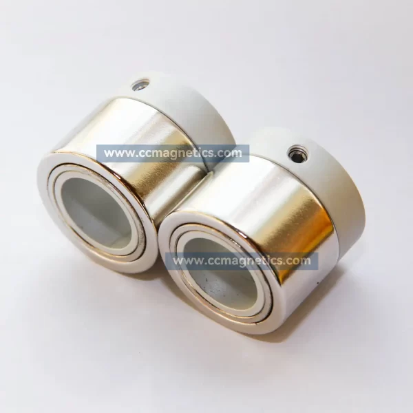
What are parallel type magnetic gears?
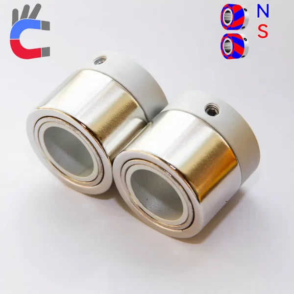
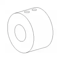
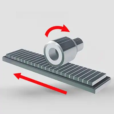
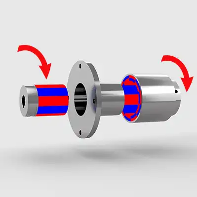
Parallel type magnetic gears, contactless torque transmission. parallel type magnetic gears are able to transmit torque between an input and an output shaft without mechanical contact. Due to their contactless torque transmission, magnetic gears are efficient and allow high rotational speeds. Furthermore, they are highly reliable and provide inherent overload protection.
Parallel type magnetic gears is non-contact power transmission device by magnetic atraction repulsion force
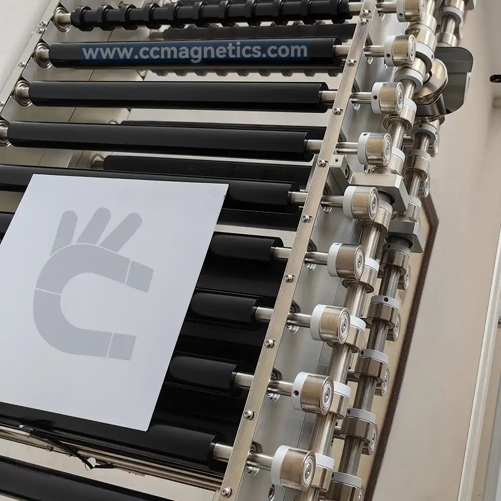
Since partition wall transmission is possible, it is widely used in clean rooms, food machinery applications, transportation equipment, conveyor, pumps, etc.
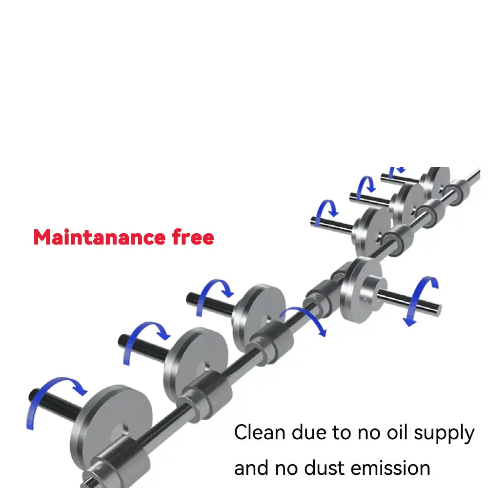
The parallel type magnetic gears eliminate micro-step vibration or driving noise caused by mechanical gears. Recommended for precision devices handling due to less influence of vibration, no wear-out of gear.
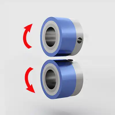
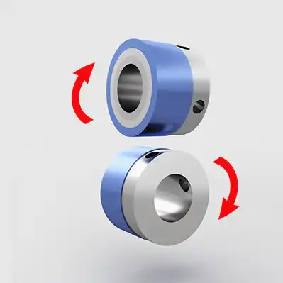
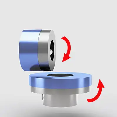
How do parallel type magnetic gears work?
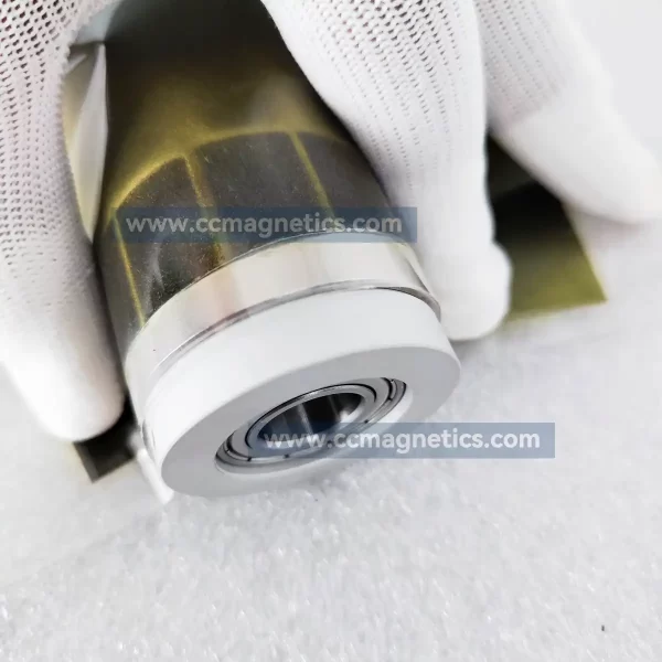
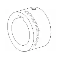
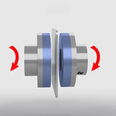
The magnetic poles of parallel type magnetic gears are tilted, so when they come into contact, they transmit torque at a right angle. This process is demonstrated in the image below.
If this magnetic transmission method is not what you need, you can also find the magnetic transmission method you need through our magnetic transmission product page.
The parallel type magnetic gears parameter
Drawing / Specifications
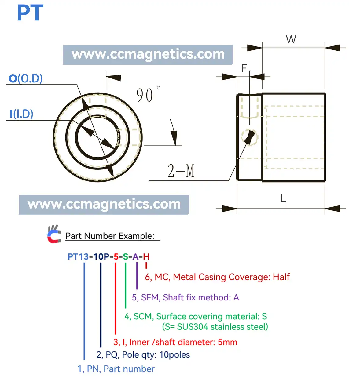
| PN | PQ | (I) I.D | SCM | SFM | MC | Tq | (O) O.D | L | W | F | M |
|---|---|---|---|---|---|---|---|---|---|---|---|
| PT13 | 10P | 5~6 | A/S | C/A | H | 2.2N.m | 13 | 15 | 10 | 2.5 | M2.5 |
| PT16 | 12P | 6~10 | A/S | C/A | H | 0.05N.m | 16 | 13 | 8 | 2.5 | M2.5 |
| PT21 | 8P | 8~12 | A/S | C/A | H | 0.2N.m | 21 | 21 | 15 | 3 | M4 |
| PT22 | 18P | 8~12 | A/S | C/A | F/H | 0.13N.m | 22 | 18 | 12 | 3 | M4 |
| PT22 | 8P | 8~12 | L/T | A | F/H | 0.13N.m | 22 | 22 | 16 | - | M4 |
| PT24 | 12P | 8~12 | A/S | C/A | F/H | 0.4N.m | 24 | 19 | 12 | 3.5 | M4 |
| PT26 | 12P | 8~15 | A/S | C/A | F/H | 0.45N.m | 26 | 21 | 14 | 3.5 | M4 |
| PT26 | 18P | 8~15 | A/S | C/A | F/H | 0.21N.m | 26 | 21 | 14 | 3.5 | M4 |
| PT27 | 8P | 8~12 | L/T | A | F/H | 0.3N.m | 27 | 22 | 15 | - | M4 |
| PT27 | 10P | 8~12 | L/T | A | F/H | 0.26N.m | 27 | 22 | 15 | - | M4 |
| PT28 | 12P | 8~15 | A/S | C/A | F/H | 0.32N.m | 28 | 25 | 14 | 3.5 | M4 |
| PT29 | 8P | 8~15 | L/T | C/A | F/H | 0.36N.m | 29 | 25 | 17 | 4 | M4 |
| PT30 | 10P | 8~15 | A/S | C/A | F/H | 0.39N.m | 30 | 25 | 18 | 3.5 | M4 |
| PT30 | 8P | 10~15 | L/T | C/A | F/H | 0.38N.m | 30 | 25 | 18 | 3.5 | M4 |
| PT30 | 10P | 10~15 | L/T | C/A | F/H | 0.35N.m | 30 | 25 | 18 | 3.5 | M4 |
| PT31 | 8P | 10~20 | L/T | A | F/H | 0.4N.m | 31 | 25 | 18 | - | M4 |
| PT31 | 10P | 10~20 | L/T | A | F/H | 0.39N.m | 31 | 25 | 18 | - | M4 |
| PT32 | 10P | 10~20 | A/S | C/A | F/H | 0.8N.m | 32 | 30 | 20 | 4 | M4 |
| PT35 | 12P | 10~20 | A/S | C/A | F/H | 1.1N.m | 35 | 32 | 21.5 | 5.25 | M5 |
| PT35 | 18P | 10~20 | A/S | C/A | F/H | 0.7N.m | 35 | 32 | 21.5 | 5.25 | M5 |
| PT36 | 08P | 10~20 | L/T | A | F/H | 0.78N.m | 36 | 32 | 22 | - | M5 |
| PT36 | 10P | 10~20 | L/T | A | F/H | 0.72N.m | 36 | 32 | 22 | - | M5 |
| PT36 | 12P | 10~20 | L/T | A | F/H | 0.58N.m | 36 | 32 | 22 | - | M5 |
| PT39 | 16P | 10~20 | A/S | C/A | F/H | 1.5N.m | 39 | 35.8 | 26.5 | 5 | M5 |
| PT40 | 12P | 10~20 | L/T | A | F/H | 0.98N.m | 40 | 36.5 | 26 | - | M5 |
| PT45 | 10P | 10~20 | A/S | C/A | F/H | 2.2N.m | 45 | 34 | 25 | 4 | M5 |
| PT53 | 10P | 20~30 | L/T | A | F/H | 1.8N.m | 53 | 37 | 26 | - | M5 |
| PT60 | 10P | 20~25 | A/S | C/A | F/H | 4N.m | 60 | 50 | 37 | 6.5 | M6 |
| PT90 | 14P | 40 | A/S | C/A | F/H | 9N.m | 90 | 70 | 40 | 15 | M6 |
| No. | Item | Description | Notes |
|---|---|---|---|
| 1 | PN | Part Number | The number after PN is the outer diameter of the magnetic coupling in millimeters. |
| 2 | PQ | Pole Quantity | Number of magnets on one magnetic coupling. |
| 3 | I | Inner Diameter | Unit of length is millimeters. |
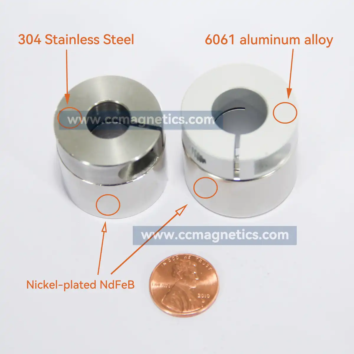
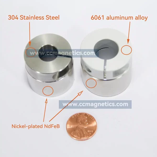
| 4 | SCM | Surface Covering Material | A=A6061 (aluminum alloy), S=SUS304 (stainless steel), L=SUS316L (stainless steel), T=TC4 (Titanium Alloy). |
| 5 | SFM | Shaft Fixing Method | Type A: Setscrew Type B: Setscrew and keyway Type C: Clamping hub slot and keyway. Refer to the drawing for the shaft fixing method. |
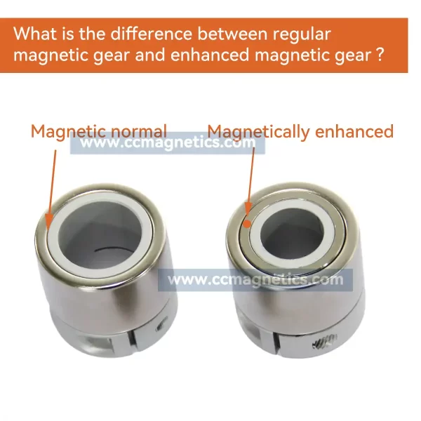
| 6 | MC | Metal Casing Coverage | F= Fully H= Half |
| 7 | Tq | Torque | The torque value shown is for a 1mm gap. |
| 8 | O | Outer diameter. | Unit of length is millimeters. |
| 9 | L,W,F,M | Unit of length on the drawing. | Unit of length is millimeters. |
Shaft fixing method
Type A
Setscrew
Type B
Setscrew and keyway
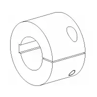
Type C
Clamping hub
slot and keyway
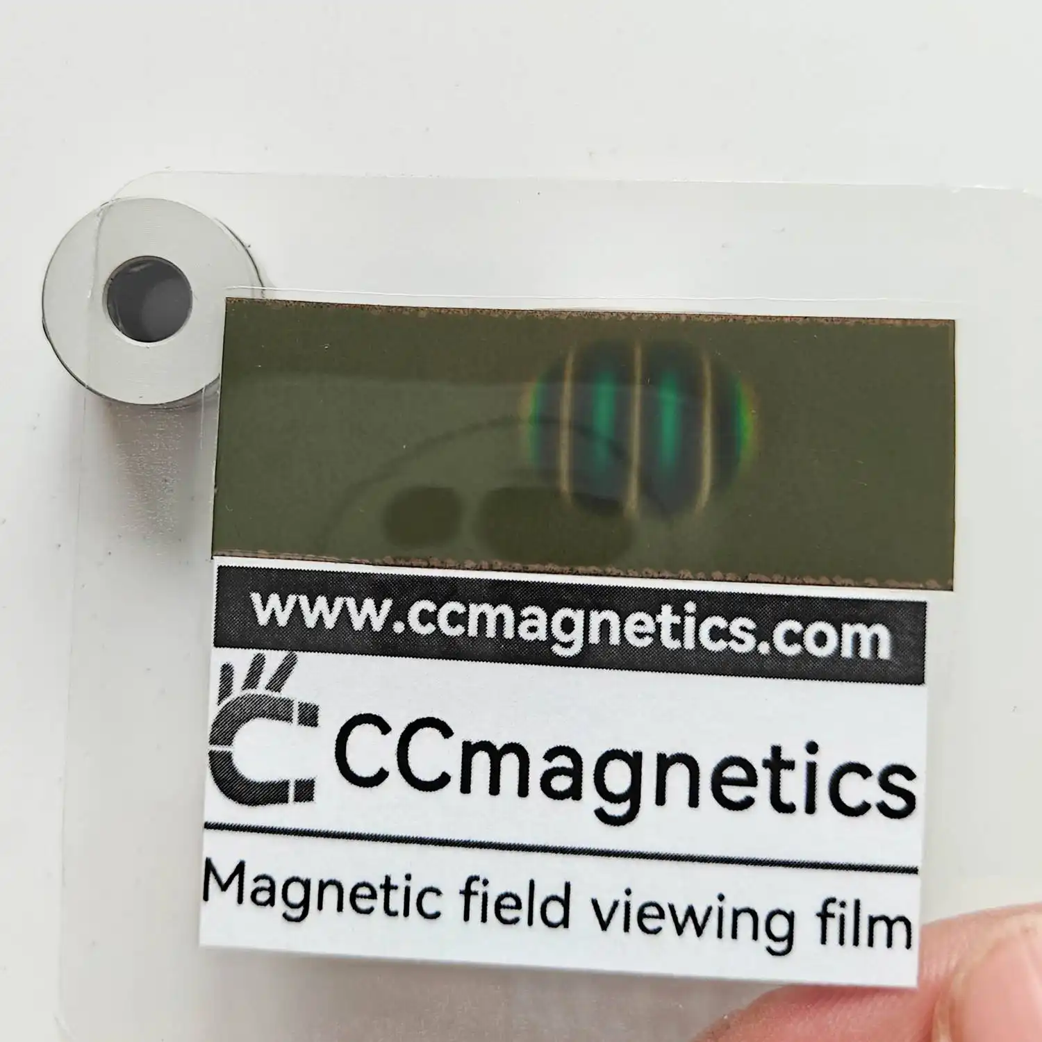
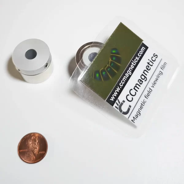
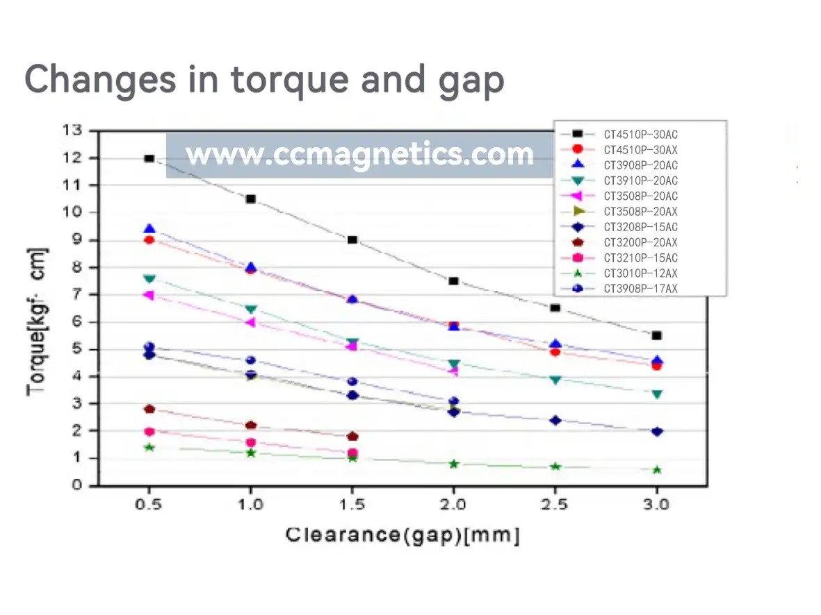
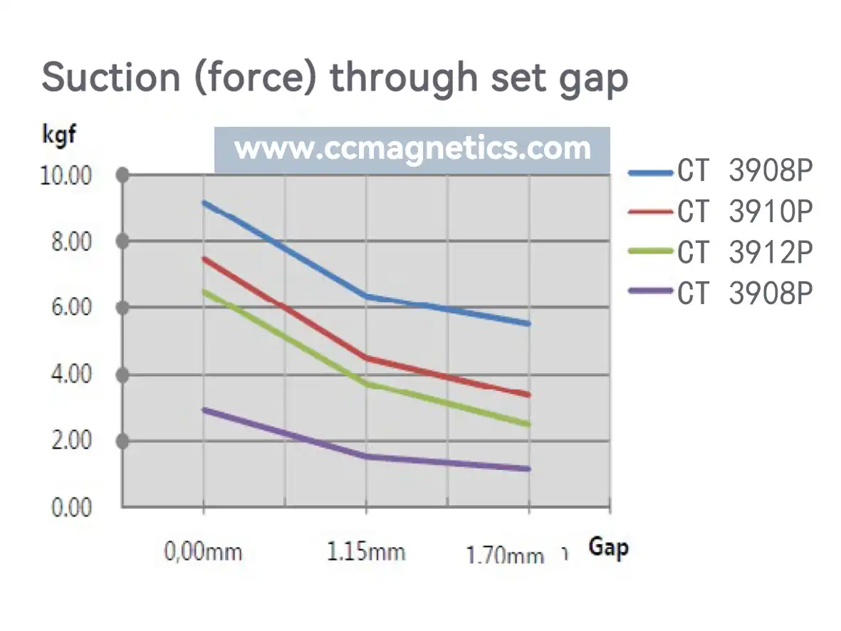
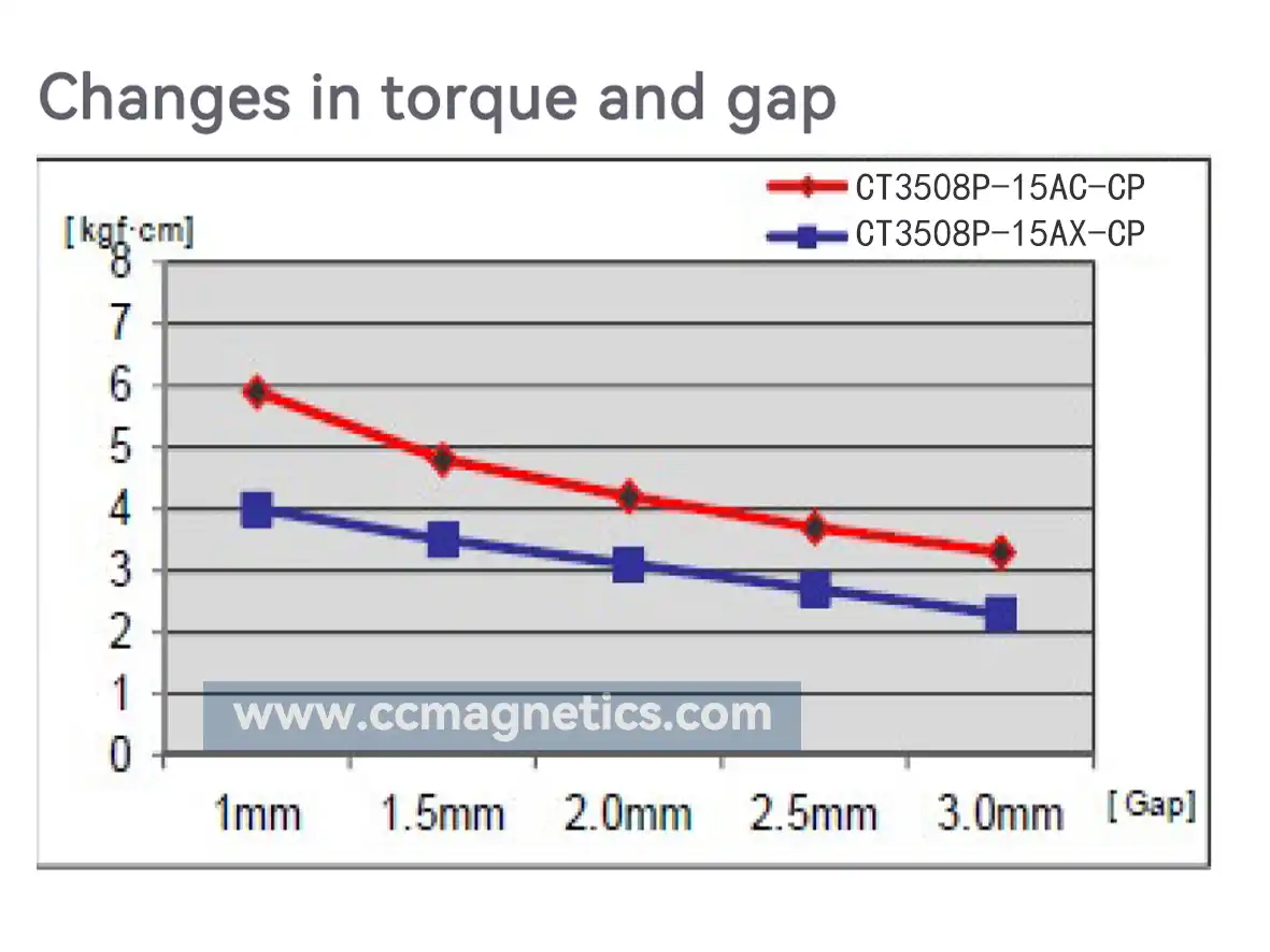
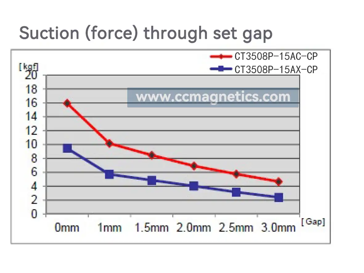
Test report of magnetic gear
Please Note:
1.Since we are magnetic gear original factory, support customization of different fixing methods.
2.Strong impacts may cause damage and lead to deterioration in magnetic force.
3.The following objects are affected by strong magnetic fields:cellphones.PCs.Watches.Pacemakers.
4.Due to its non-contact design.it is not suitable for extremely high-speed rotation.(Max.speed:1500 rpm).
5.The operating temperature is -20°C-80°C. Since we are an original factory, we can customize it to: -20°C-150°C.
18562644213 –
good quality and nicely packed
suchitiru –
Great!
313184103 –
thank you a lot.