
 Deutsch
 Русский
 Español
 Français
 한국어
한국어 日本語
日本語
A magnetic encoder is an indispensable sensor in motion control systems, used to measure the angular displacement, linear displacement, velocity, and acceleration of mechanical motion. Among them, magnetic encoders are widely used in the industrial field due to their excellent pollution resistance and durability. Based on their different output signals, magnetic encoders are mainly divided into two major categories: Incremental Encoders and Absolute Encoders.
1. Incremental Encoder
An incremental encoder is a device that utilizes the magnetic field changes of a magnetic ring (or magnetic scale) to generate periodic electrical signals, thereby measuring relative displacement.

1.1 Basic Working Principle
- Magnetic Ring Structure: The incremental magnetic ring has N-pole and S-pole magnetic pole pairs of equal width arranged alternately along its circumference.
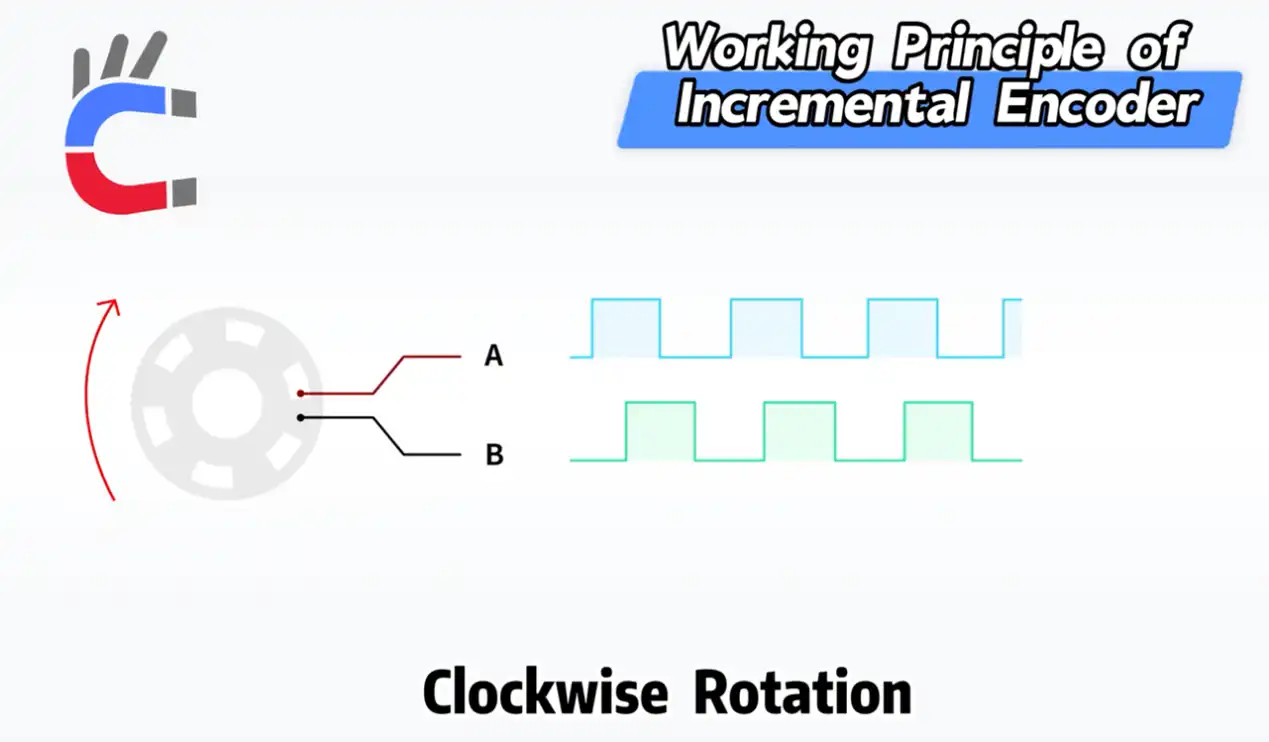
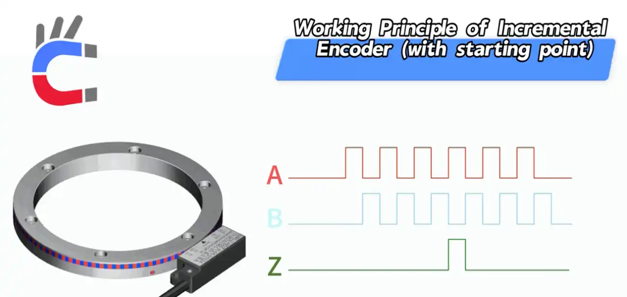
- Signal Generation: Sensors (such as magnetoresistive sensors or Hall sensors) read the magnetic field changes on the rotating magnetic ring and generate two square wave signals with a phase difference of 90°, typically referred to as Phase A and Phase B (or sine/cosine signals).
- The number of magnetic pole pairs determines the resolution of the encoder (one magnetic pole pair corresponds to one signal period).
- Displacement Measurement: During each rotation, Phase A and Phase B will output a series of pulses. The system calculates the displacement amount by counting the number of these pulses.
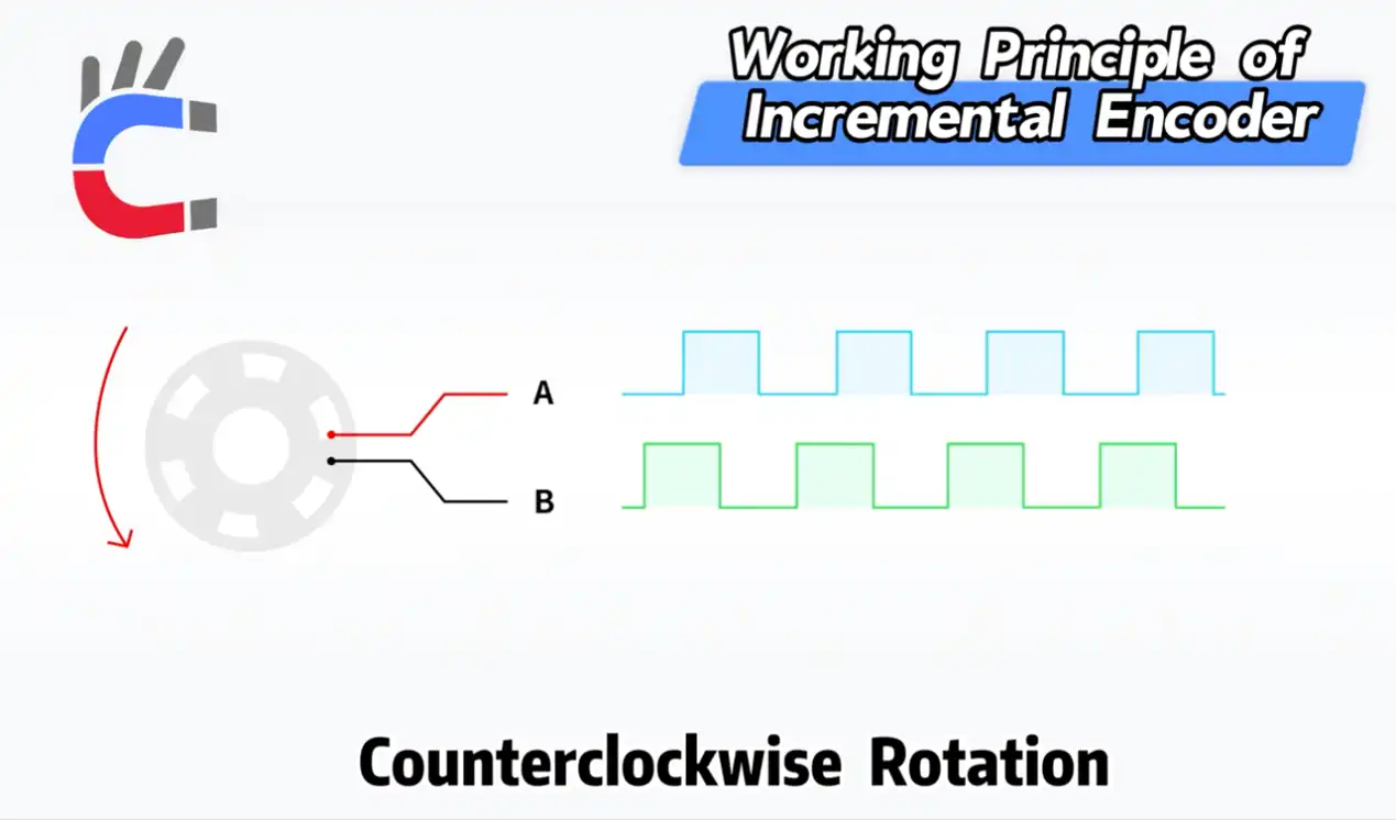
- Direction Determination (Quadrature Decoding): The 90° phase difference between Phase A and Phase B is used to determine the rotation direction.
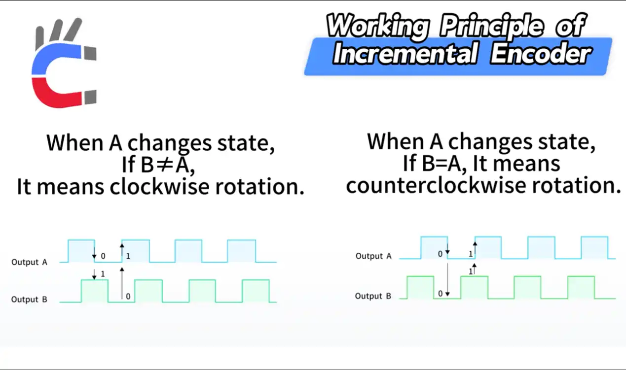
- Clockwise Rotation: When Phase A changes state, if B ≠ A (i.e., Phase B lags Phase A), it indicates clockwise rotation.
- Counterclockwise Rotation: When Phase A changes state, if B = A (i.e., Phase A lags Phase B, or Phase B leads Phase A), it indicates counterclockwise rotation.
- Clockwise Rotation: When Phase A changes state, if B ≠ A (i.e., Phase B lags Phase A), it indicates clockwise rotation.
1.2 Characteristics of Incremental Encoders
- Relative Position: Incremental encoders only provide relative displacement information, meaning the amount of displacement change starting from the last measurement point.
- Power-off Memory: They do not possess a power-off memory function. Once the system loses power, the pulse counter resets to zero, and the encoder cannot know the current position. After powering on again, it must find a reference point (homing operation) to determine the absolute position.
- Industrial Applications: Suitable for scenarios such as speed control and fixed-length cutting, where knowing the exact position at the moment of startup is unnecessary, but precise measurement of motion speed and relative distance is required.
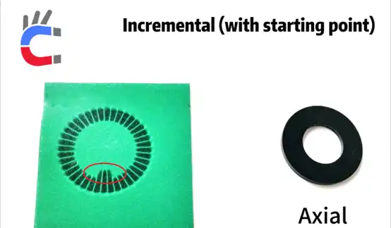
2. Incremental Encoder with Index/Reference Mark
To solve the problem of incremental encoders needing to return to zero after a power outage, an "origin" or "zero position" signal was introduced, also known as the Z Phase or Reference Mark.

2.1 Working Principle
- Z Phase Signal: In addition to Phase A and Phase B, a unique reference mark (usually a special magnetic pole or gap) is added to the magnetic ring. It generates only one pulse signal per full rotation, which is the Z Phase signal.
- Determining Absolute Position:
- The encoder starts rotating after powering on.
- When the Z Phase pulse appears, the system clears the current pulse count to zero or sets it to a known initial absolute position. This Z pulse point serves as the "origin."
- Thereafter, by counting the A/B pulses, the absolute position relative to the origin can be known.
- Practical Application Logic: The "squeaking" sound mentioned in the video when a printer starts up is the process of the incremental encoder searching for the Z Phase origin. In industrial control, this process is called Homing, which is a crucial step that must be completed before startup.
2.2 Industrial Applications
Commonly used in equipment that requires a homing operation to establish a coordinate system, such as machine tools, robots, and printers. Its advantage lies in having a lower cost than absolute encoders while still being able to obtain the absolute position through the homing operation.
2.3 Signal Processing of Incremental Encoders: Quadrature Decoding and Multiplication
Incremental encoders output Phase A, Phase B, and Phase Z signals. These are typically differential signals (such as RS-422) to enhance anti-interference capability.
- Core of Signal Processing: Quadrature Decoding
The controller (such as a PLC or motion control card) needs to process the A/B signals to obtain position and direction information:
- Direction Determination: Based on the phase difference (90°) between Phase A and Phase B, determine the rotation direction (clockwise/counterclockwise).
- Pulse Counting: Accumulate or decrement the pulses based on the direction to obtain the total displacement amount.
- Improving Precision: Multiplication Technology
To improve position resolution, the original pulses are usually not counted directly; instead, multiplication technology is employed:
- 1X Multiplication: Counting occurs only on the rising edge of Phase A.
- 2X Multiplication: Counting occurs on both the rising and falling edges of Phase A.
- 4X Multiplication: Counting occurs on all edges (rising and falling edges) of both Phase A and Phase B. This is the most commonly used method, quadrupling the nominal resolution of the encoder.
Assuming an encoder has N pulses per revolution (PPR), after applying 4X multiplication, the actual resolution received by the controller becomes 4N counts per revolution (CPR).
- Velocity Calculation
Velocity calculation is achieved by taking the total number of pulses received within a unit of time.
$$Rotation Speed (RPM) = \frac{Pulse Count \times 60}{Time Interval (s) \times CPR}$$
Rotation Speed (RPM)
- Full Name: Revolutions Per Minute.
- Meaning: This is the final calculated result, representing the number of full revolutions a device (e.g., motor shaft, wheel) makes per minute. This is the most commonly used unit of rotational speed in engineering and mechanical fields.
Pulse Count
- Meaning: The total number of pulses detected by the encoder or sensor within your set time interval.
- Physical Significance: During the rotation of the encoder, it outputs one electrical pulse every time it rotates past a specific angle. The more pulses there are, the greater the angle or number of revolutions turned within the same time period.
Time Interval (s)
- Unit: Seconds (s).
- Meaning: This is the time period you use to measure the pulse count. For example, if you counted 50 pulses within 0.1 seconds, then the "time interval" here is 0.1 seconds.
CPR
- Full Name: Counts Per Revolution.
- Meaning: This is an inherent parameter of the encoder or sensor you are using. It indicates how many counts the device outputs for every single full rotation (360 degrees).
- Criticality: This is a fixed value, which you need to determine based on the specifications manual of the device you are using.
- Zero Position / Origin Processing (Z Phase)
The Z Phase signal is used to calibrate the absolute position. During system startup or homing:
- The system moves at a high speed to search for the Z Phase pulse.
- When the Z Phase pulse (usually with a width of 1 to 2 A/B pulse periods) appears, the controller immediately resets the counter to zero or sets it to a preset absolute starting position.
3. Absolute Encoder
An absolute encoder provides a unique digital code to represent its absolute position throughout the entire rotation cycle.

3.1 Definition and Advantages of Absolute Position
- Absolute Position: Every measurement directly outputs a digital code corresponding to the current angle, and this code is unique between 0° and 360°. For any given angle of the shaft (e.g., 10.5°, 180°, 359.9°), the encoder will output a one-of-a-kind digital code. Every position has its own "ID number."
- Power-off Memory: The biggest advantage is that it features power-off memory. No matter when power is applied, it can immediately output the current position without the need for homing.
3.2 Working Principle of Absolute Encoders
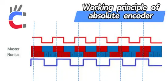
Absolute magnetic encoders typically adopt multi-track or Nonius principles to achieve absolute positioning. The diagram below illustrates a single-turn absolute encoder based on the Nonius principle.
3.2.1 Nonius Principle
The core of the Nonius principle is the use of two magnetic tracks (magnetic rings) with different numbers of magnetic pole pairs, determining the absolute position through the difference in their signal periods.
- Magnetic Ring Structure: Two magnetic tracks are employed:
- Master Track: Assuming the number of magnetic pole pairs is P (e.g., 6 pole pairs as shown in the video).
- Nonius Track: The number of magnetic pole pairs is P-1 (e.g., 5 pole pairs as shown in the video).
- Signal Generation and Calculation:
- Fine Resolution: The two tracks generate two sets of sine/cosine signals respectively (e.g., Sine(MT) and Sine(NT)), which are used to calculate the fine position within one magnetic pole period. This is achieved through the electrical signal interpolation technique.
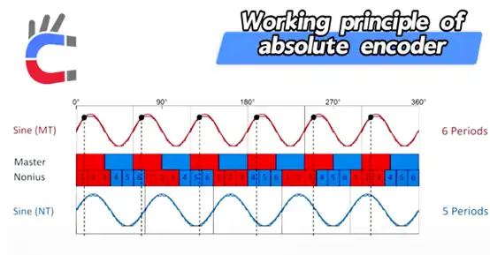
- Coarse Resolution: Because the two tracks have different numbers of magnetic poles, the phase difference between them will change periodically as they rotate.
- Within a complete 360° rotation cycle, the master track and the Nonius track will generate a total phase shift (or count difference) that changes from 0° to 360°.
- This unique phase shift can serve as a master magnetic pole period count, used to distinguish which master magnetic pole period the encoder is currently located in.
- Fine Resolution: The two tracks generate two sets of sine/cosine signals respectively (e.g., Sine(MT) and Sine(NT)), which are used to calculate the fine position within one magnetic pole period. This is achieved through the electrical signal interpolation technique.
- Absolute Position Calculation Formula:
Absolute Position = Master Period Count + Master Interpolation
3.3 Types of Absolute Encoders
- Single-turn Absolute: Measures the absolute angle within the 0°-360° range, but cannot record the number of revolutions.
- Multi-turn Absolute: On the basis of single-turn absolute positioning, a gear set or other counting mechanism is added to record the number of rotations, thereby providing a larger absolute position range.
3.4 Industrial Applications
Absolute encoders are the top choice for high-performance servo systems. Their characteristic of not requiring homing greatly enhances equipment efficiency and safety:
- Robotics and Automation: Used for precise position control of robot joints and arm spans.
- CNC Machine Tools: Precise position feedback for the main spindle and feed axes.
- Heavy Machinery: Cranes, port machinery, etc., ensuring the current position information is retained under any power failure situation.
- Permanent Magnet Synchronous Motor (PMSM) Commutation: After the drive is powered on, electronic commutation can be performed directly using the absolute position information, achieving immediate and smooth motor startup.
3.5 Signal Processing of Absolute Encoders: Serial Communication Protocols
Absolute encoders directly output digital position codes; therefore, the core of their signal processing is the communication protocol, ensuring the accuracy and real-time performance of data transmission.
- Typical Protocols: BiSS-C and SSI
| Protocol | SSI (Synchronous Serial Interface) | BiSS-C (Bi-directional/Synchronous Serial) |
|---|---|---|
| Type | Unidirectional, synchronous serial communication | Bidirectional, synchronous serial communication (most common) |
| Principle | The controller sends out a Clock signal, and the encoder synchronously transmits the position Data out. | Includes the unidirectional function of SSI, and adds a return channel to read and write encoder parameters. |
| Characteristics | Simple, stable, moderate real-time performance. | High speed, high real-time performance (nanosecond-level latency), used for high-performance servo systems. |
| Data Content | Primarily position data. | Position data + Checksum (CRC) + Warning/Diagnostic information. |
- Signal Processing Flow (Taking BiSS-C as an example)
- Clock Generation: The servo drive (controller) generates a high-speed clock signal (typically from a few MHz to 10 MHz).
- Data Request: The controller notifies the encoder to send data via the clock signal.
- Data Transmission: The encoder synchronously transmits up to several dozens of bits of digital position code, CRC checksum, and fault status bits to the controller.
- Verification and Parsing:
- CRC Verification: The controller performs a Cyclic Redundancy Check on the received data. If verification fails, the data is considered incorrect, which typically triggers an alarm or uses the position from the previous cycle.
- Parsing: Parses the data stream to extract high-precision position words, such as 24-bit or 26-bit.
- Application of Absolute Encoders in Servo Control
The characteristic of absolute encoders not requiring a homing operation makes them the preferred choice for high-performance servo systems:
- Positioning upon Power-on: After the servo drive is powered on, the absolute angle of the motor can be obtained through a single communication, eliminating the need to waste time homing.
- Electronic Commutation: For Permanent Magnet Synchronous Motors (PMSM), the exact initial position of the rotor must be known to correctly output starting torque. Absolute encoders provide this information directly, allowing the drive to perform electronic commutation straight away and start the motor smoothly and immediately. Conversely, incremental encoders require a "zero-finding" or "initial angle identification" process first.
In summary, the signal processing of incremental encoders focuses on hardware counting and software multiplication; whereas the signal processing of absolute encoders focuses on high-speed serial communication and data verification.
4. Summary Comparison: Incremental vs. Absolute Encoders
| Characteristic | Incremental Encoder | Incremental Encoder with Index/Reference Mark | Absolute Encoder |
|---|---|---|---|
| Position Output | Number of pulses (Relative position) | Number of pulses (Relative position) | Unique digital code (Absolute position) |
| Power-off Memory | No | No | Yes |
| Startup Operation | Must home (search for Z phase) | Must home (search for Z phase) | No homing required |
| Signal Type | A/B phases (Square wave / Sine-cosine) | A/B phases + Z phase | Multi-track code / Nonius signal |
| Complexity & Cost | Low | Medium | High |
| Typical Applications | Speed control, conveyors | Machine tool homing, printers | Robot joints, high-precision positioning |