
 Deutsch
 Русский
 Español
 Français
 한국어
한국어 日本語
日本語
An Encoder is an essential sensor in motion control systems. It is used to measure angular displacement (angle changes), linear movement, speed, and acceleration of mechanical parts. Among these, Magnetic Encoders are widely used in industrial fields because they are highly durable and resistant to dirt and oil.
Based on their output signals, magnetic encoders are divided into two main categories: Incremental Encoders and Absolute Encoders.
1. Incremental Encoder
An incremental encoder creates periodic electrical signals by detecting changes in the magnetic field of a rotating magnetic ring. It is used to measure relative displacement (how much the object has moved from its previous position).
1.1 Basic Working Principle
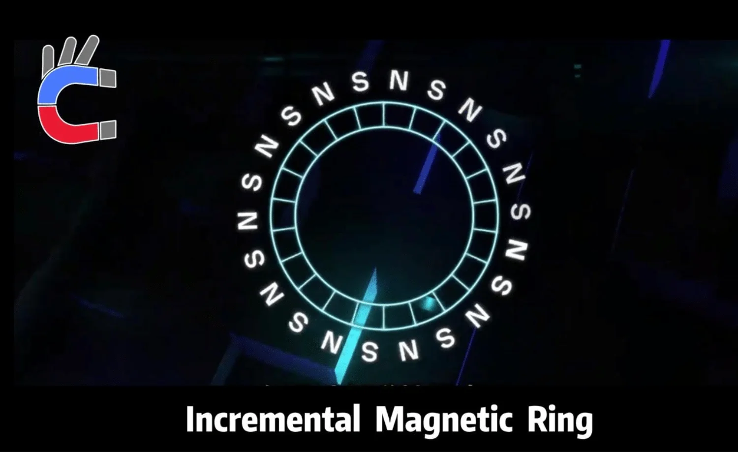
- Magnetic Ring Structure: The ring has North (N) and South (S) magnetic poles arranged alternately around it.
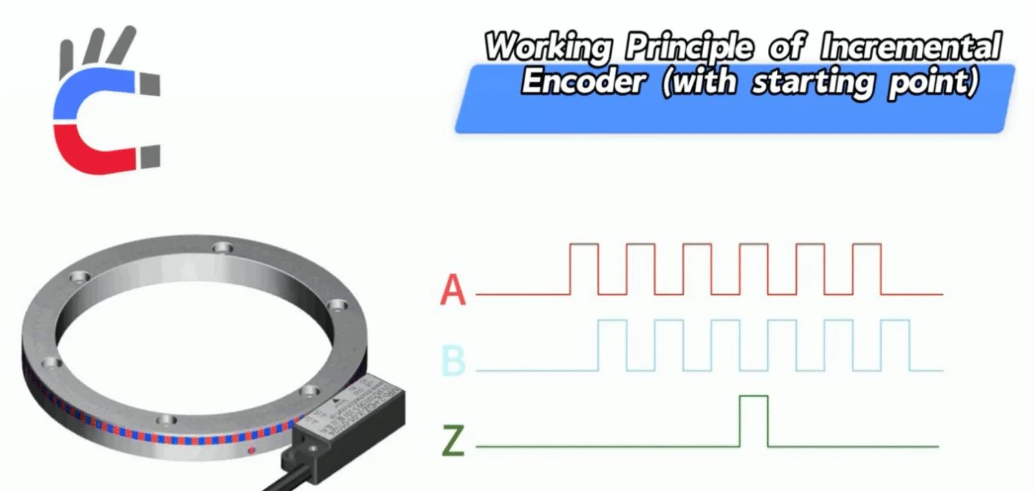
- Signal Generation: A sensor (such as a Hall sensor or Magnetoresistive sensor) reads the magnetic changes as the ring spins. It generates two square wave signals, usually called Phase A and Phase B. These two signals are offset by 90 degrees.The number of magnetic pole pairs determines the resolution of the encoder (one pair equals one signal cycle).
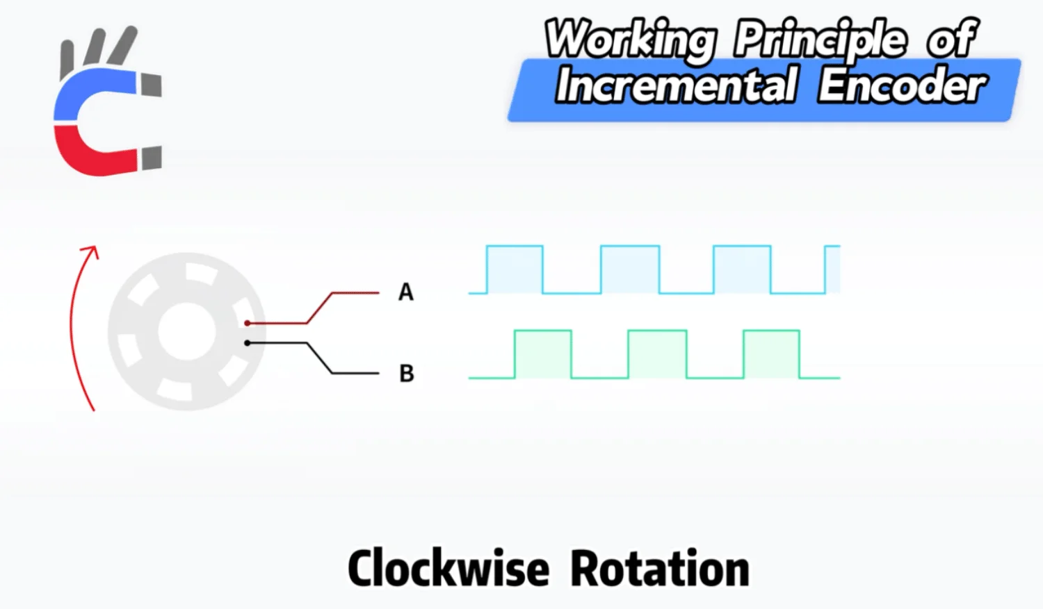
- Measuring Displacement: Every time the ring rotates, Phase A and Phase B output a series of pulses. The system calculates the distance moved by counting these pulses.
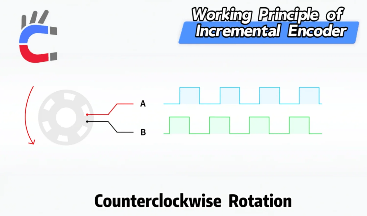
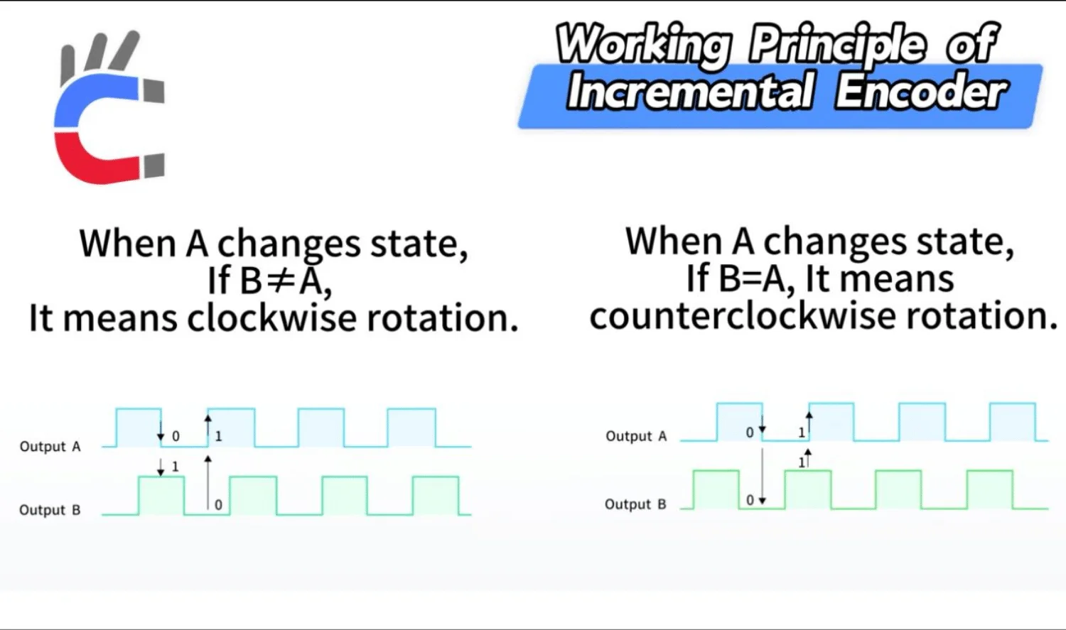
- Determining Direction (Quadrature Decoding): The 90-degree phase difference between Phase A and Phase B is used to figure out the direction of rotation.Clockwise Rotation: When Phase A changes, if Phase B lags behind Phase A.Counter-clockwise Rotation: When Phase A changes, if Phase B leads Phase A.
1.2 Characteristics of Incremental Encoders
- Relative Position: It only provides information about relative movement. It tells you "how far" it moved from the last point.
- No Power-off Memory: It does not remember its position if the power is cut. Once the system loses power, the pulse counter resets to zero. When power returns, the system must find a reference point (a process called "Homing") to know its absolute position.
- Industrial Application: Suitable for applications that need speed control or cutting to a specific length. It is ideal for situations where knowing the exact starting position immediately upon power-up is not strictly necessary.
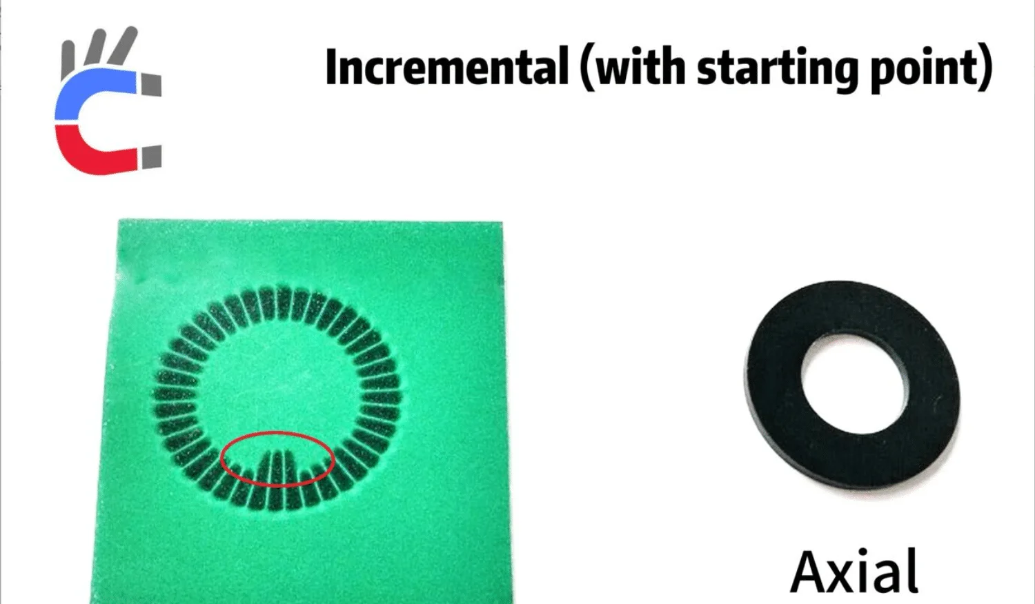
2. Incremental Encoder with a Reference Point (Z-Phase)
To solve the problem of losing position after a power cut, manufacturers add a "Zero" or "Reference" signal, also known as the Z-Phase.

2.1 How It Works
- Z-Phase Signal: In addition to Phase A and Phase B, the magnetic ring has a unique reference mark. It produces just one pulse per revolution.
- Finding Absolute Position:The encoder starts rotating after being powered on.When the system detects the Z-Phase pulse, it resets the current pulse count to zero (or a set starting value). This Z-pulse acts as the "Home" position.From this point on, the system knows the absolute position relative to this home point by counting A/B pulses.
2.2 Industrial Application
This is commonly used in CNC machines, robots, and printers. The "buzzing" sound a 3D printer makes when it first turns on is often the machine searching for this Z-Phase (Homing) to establish its coordinates.
2.3 Signal Processing: Quadrature Decoding and Multiplication
To improve accuracy and resistance to interference, the signals (A, B, and Z) are often differential (e.g., RS-422 standard).
- Quadrature Decoding: The controller (like a PLC) analyzes the A/B signals to decide direction and count pulses.
- Multiplication (Improving Precision): Instead of counting just once per cycle, engineers use "Multiplication" techniques to increase resolution:1X: Counts only at the rising edge of Phase A.2X: Counts at both the rising and falling edges of Phase A.4X: Counts at all edges (rising and falling) of both Phase A and Phase B. This is the most common method, as it quadruples the encoder's nominal resolution.
3. Absolute Encoder
An Absolute Encoder provides a unique digital code that represents its exact position within a full rotation.

Single-Track Sensor Rings
3.1 Definition and Advantages
- Absolute Position: Every measurement outputs a specific digital code corresponding to the current angle. From 0° to 360°, every position has a unique "ID card."
- Power-off Memory: The biggest advantage is that it remembers its position even without power. Whenever you turn it on, it immediately knows where it is. No "Homing" or "Zeroing" is required.
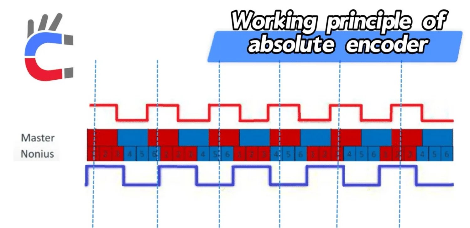
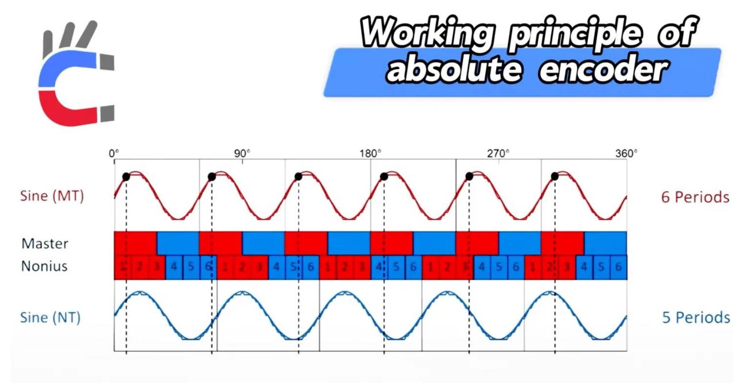
3.2 Working Principle: The Nonius (Vernier) Principle
Absolute magnetic encoders often use a multi-track system, known as the Nonius or Vernier principle, to achieve absolute positioning.
- Magnetic Structure: It uses two magnetic tracks:Master Track: Contains
PPpole pairs (e.g., 6 pairs).Nonius Track: ContainsP−1P−1pole pairs (e.g., 5 pairs). - Calculating Position:**Fine Resolution:** Generated by the sine/cosine signals from the tracks.Coarse Resolution: Because the two tracks have different numbers of poles, the phase difference between them changes periodically as they rotate. By measuring this phase difference, the system can calculate exactly which "sector" (or period) the encoder is currently in within a full 360° rotation.
3.3 Types of Absolute Encoders
- Single-Turn: Measures absolute angles within 0°–360° but does not count how many full circles have been turned.
- Multi-Turn: Adds a gear system or a counter to record the number of full revolutions, providing a much larger range of absolute positioning.
3.4 Industrial Applications
Absolute encoders are the top choice for high-performance servo systems because they eliminate the need for homing, improving efficiency and safety.
- Robotics: For precise control of robot joints and arms.
- CNC Machines: For exact feedback on spindles and feed axes.
- Heavy Machinery: Cranes and port equipment, ensuring position is known even after a power failure.
- PMSM Motors (Permanent Magnet Synchronous Motors): These motors need to know the rotor's exact position immediately to start smoothly. Absolute encoders provide this data for instant Electronic Commutation.
3.5 Signal Processing: Serial Communication Protocols
Since absolute encoders output digital codes rather than simple pulses, they use communication protocols to transfer data accurately and quickly.
Typical Protocols: BiSS-C and SSI
| Feature | SSI (Synchronous Serial Interface) | BiSS-C (Bidirectional Serial) |
|---|---|---|
| Type | One-way, Synchronous | Two-way, Synchronous (Most Common) |
| Principle | Controller sends a Clock signal; Encoder sends back Position Data. | Includes the features of SSI but adds a channel to send data back to the encoder (like parameters). |
| Performance | Simple, stable. | High speed, very low delay (latency), used in high-end servos. |
| Data Content | Mostly Position Data. | Position Data + CRC Check (Error checking) + Warnings/Diagnostics. |
Signal Processing Flow (Example using BiSS-C):
- Clock Generation: The drive (controller) creates a high-speed clock signal (MHz).
- Data Request: The controller asks for data using the clock signal.
- Transmission: The encoder sends the digital position code, CRC check code, and status bits.
- Verification & Decoding:**CRC Check:** The controller checks for errors. If the data is bad, it triggers an alarm.Decoding: The controller extracts the high-precision position data (e.g., 24-bit or 26-bit).

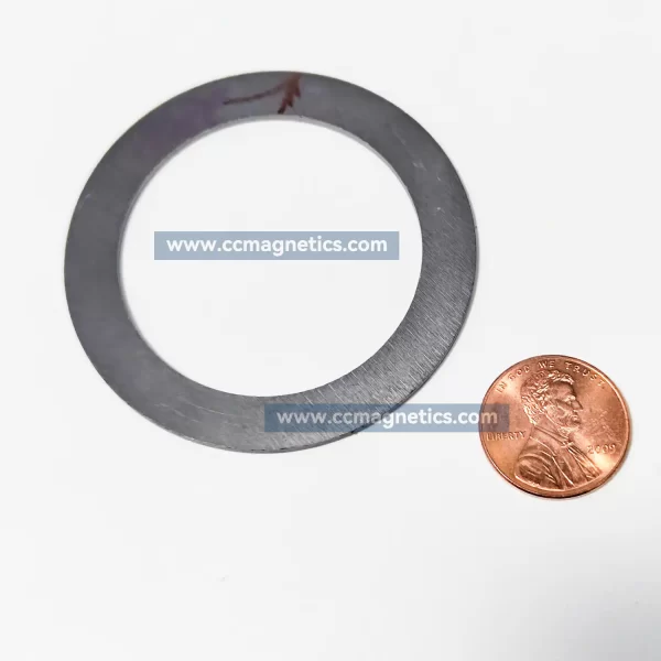
Dual-Track Encoder Ring
Ferrite Magnetic Rings for iC-MU128/150/200 Absolute Encoders
4. Summary: Incremental vs. Absolute Encoders
| Feature | Incremental Encoder | Absolute Encoder |
|---|---|---|
| Position Output | Pulse Count (Relative Position) | Unique Digital Code (Absolute Position) |
| Power-Off Memory | No. Data is lost when power is cut. | Yes. Position is retained. |
| Startup Operation | Must perform "Homing" (Find Z-phase). | Instant operation. No homing needed. |
| Signal Type | A/B Phase (Square Wave / Sine Wave) | Serial Data (SSI, BiSS-C) |
| Complexity & Cost | Low | High |
| Typical Application | Speed control, conveyor belts | Robot joints, high-precision positioning, CNC |
In conclusion, Incremental Encoders rely on hardware counting of pulses and are cost-effective for speed monitoring. Absolute Encoders rely on high-speed serial communication and data verification, making them the standard for high-precision, safety-critical positioning tasks.