
 Deutsch
 Русский
 Español
 Français
 한국어
한국어 日本語
日本語
Legal Disclaimer:
All product names, trademarks, and registered trademarks (including iC-Haus, iC-MU, iC-PVS, and iC-PZ) are the property of their respective owners. References to these trademarks are made solely for purposes of technical compatibility, engineering reference, and technical information sharing, and do not imply any affiliation, sponsorship, or endorsement. Reproduction and distribution of this article are welcome, provided that a direct link to the original source is included.
In the design of high-performance magnetic encoders, selecting the correct magnetic target (such as a magnetic pole wheel, diametrical magnet, or ferromagnetic steel gear) is a critical system-level decision. This choice directly determines the encoder's ultimate accuracy, resolution, mechanical envelope, thermal limits, and overall system cost. System architects suggest that it is essential to understand how magnetic target characteristics directly couple into the control loop.
This guide provides a comprehensive, multi-dimensional selection framework to help engineers navigate the target selection process for industrial, robotic, and medical applications.
1. Mechanical Constraints: Hollow vs. Solid Shaft
The physical structure of the motor or rotating assembly represents the first selection filter.
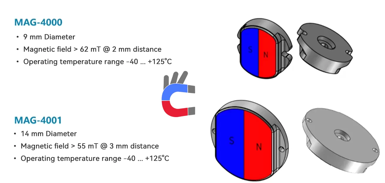
- Solid Shaft (On-Axis Layout): For applications where the end of the rotating shaft is accessible, diametrical magnets are the standard choice. These are typically small, cost-effective cylindrical magnets (e.g., the 9 mm MAG4000 or 14 mm MAG4001) mounted directly to the shaft end.
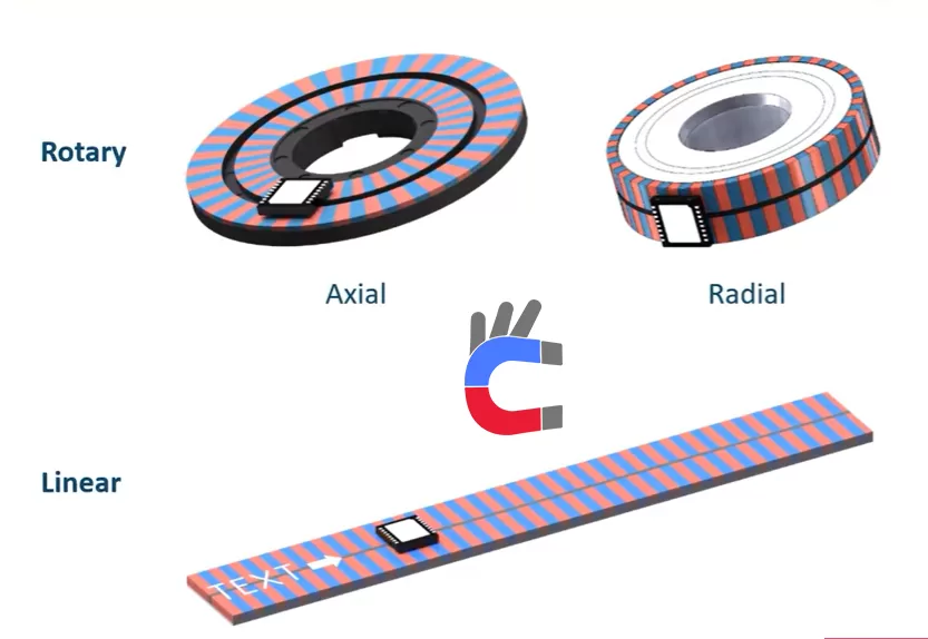
- Hollow Shaft (Off-Axis Layout): For applications requiring a hollow shaft (e.g., robotic joints where cabling or liquid lines must pass through the center), radial or axial multi-pole wheels are required. These rings slide over the shaft, allowing a hollow center.
- Passive Scanning (Back-Bias Setup): In environments where mounting a delicate magnetic component on the shaft is impossible, a passive ferromagnetic steel gear can act as the target, paired with a sensor that has a back-bias permanent magnet positioned behind it.
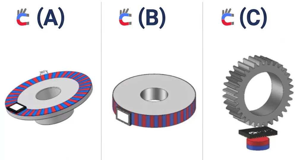
Figure 1: Core Mechanical Mounting Architectures (Text-Free)
- (A) On-Axis layout featuring a single-pair diametrical magnet on the shaft end.
- (B) Off-Axis layout utilizing a multi-pole radial magnetic wheel for hollow-shaft designs.
- (C) Gear Wheel scanning layout using a passive ferromagnetic steel gear and a back-bias magnet.
2. Accuracy & Resolution Requirements
The target configuration must match the feedback requirements of the motion control system.

- Incremental Positioning: Single-track magnetic targets with uniformly distributed pole pairs (e.g., a pole width of exactly 2 mm) are ideal for incremental feedback or high-speed commutation.
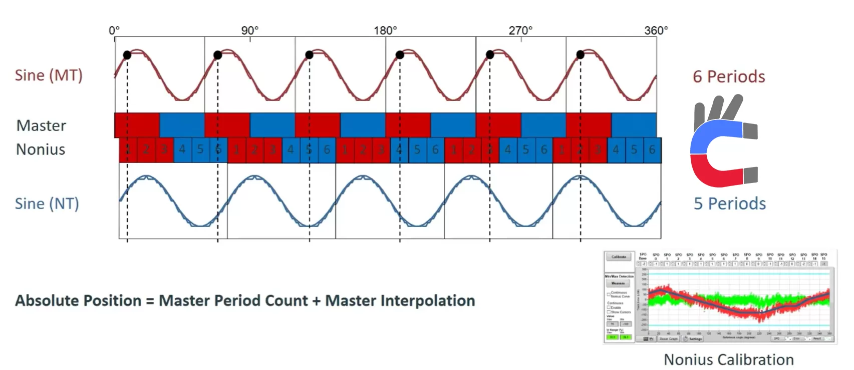
- Absolute Single-Turn Positioning (Vernier/Nonius Principle): For absolute positioning without a startup homing run, dual-track Vernier (Nonius) magnetic targets must be used. These targets feature a Master Track with N pole pairs and a parallel Nonius Track with N-1 pole pairs (e.g., 64/63 or 32/31 pairs). The encoder chip calculates the continuous phase difference between the two tracks to determine the unique absolute angle at startup.
- SPO Parameter Calibration: To ensure high accuracy across dual-track systems, fine-tuning and calibrating the SPO (Sensor-to-Target Phase Offset) parameters within the encoder IC is necessary to align the mechanical relationships of the tracks.
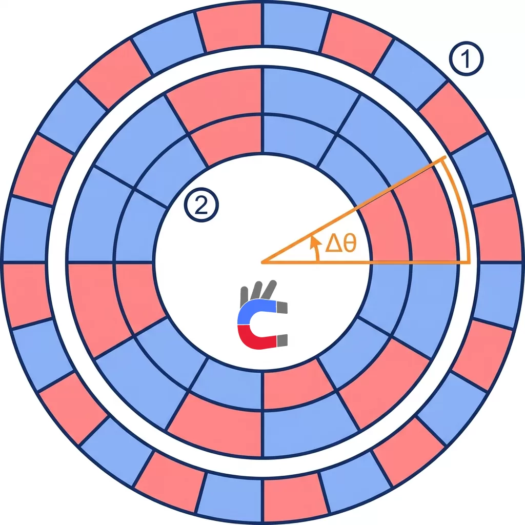
Figure 2: Double-Track Vernier Nonius Absolute Positioning Principle (Text-Free)
- (1) Master Track: The primary, high-resolution absolute track containing N magnetic pole pairs.
- (2) Nonius Track: The auxiliary track containing fewer (N-1) magnetic pole pairs.
- Δθ: The continuous angular phase difference used to calculate the absolute position.
3. Sensor Technology & Compatibility (TMR vs. Hall)
Choosing a magnetic target requires careful consideration of the transducer technology utilized in the encoder IC.
- Traditional Hall-Effect Sensors: These devices detect the vertical magnetic field component (BZ) perpendicular to the chip surface.
- Tunneling Magnetoresistive (TMR) Sensors: Modern high-performance chips utilize TMR technology, which detects the planar magnetic field component (BXY) parallel to the chip surface.
- Engineering Advantages of TMR: TMR technology offers a 100x sensitivity boost over Hall-effect sensors (hundreds of millivolts compared to a few millivolts of raw signal) and extremely low magnetic hysteresis of just 0.04° (compared to 0.2° for AMR). This extreme sensitivity allows engineers to select smaller, weaker, or cheaper magnets and operate with significantly larger air gaps (working clearance) and looser mechanical mounting tolerances.
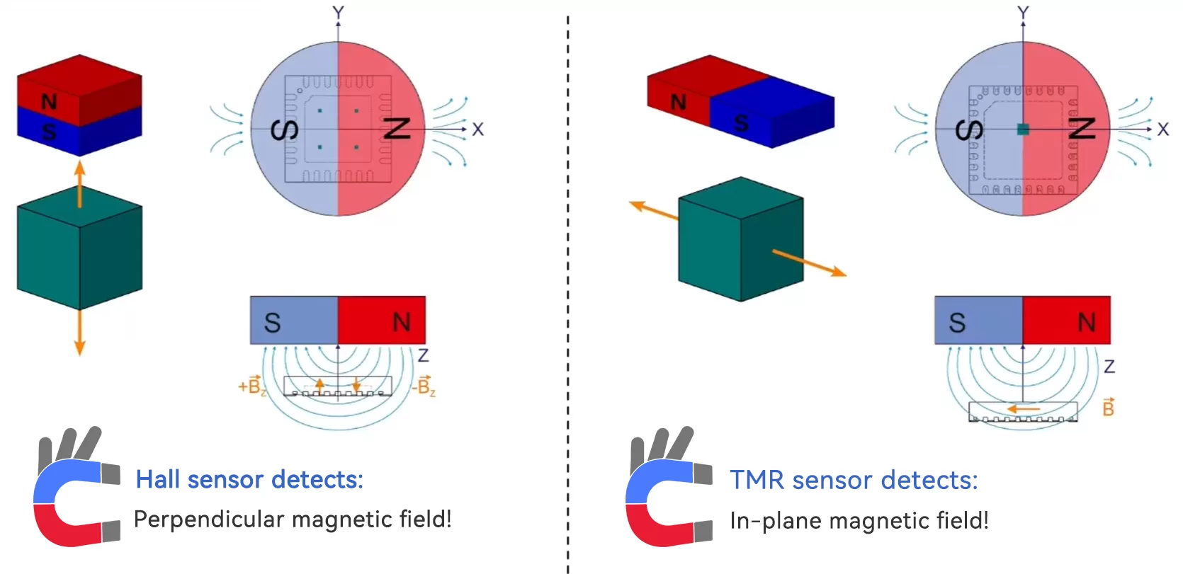
Figure 3: Transducer Detection Planes and Technology Comparison (Text-Free)
- (A) Traditional Hall sensor setup detecting the perpendicular vertical magnetic field component (BZ).
- (B) Advanced TMR sensor setup detecting the parallel planar magnetic field component (BXY).
4. Environmental Robustness & Material Selection
The operating environment dictates the material properties of the magnetic target.
- Active Magnetic Wheels (Elastomer / Plasto-Ferrite / Hard Ferrite): These magnetic encoder targets are primarily divided into plasto-ferrite and hard-ferrite materials. Plasto-ferrite wheels consist of magnetic powder bonded with rubber or plastic; while cost-effective, they are susceptible to thermal expansion and have a maximum operating temperature limit of 120°C. In contrast, hard-ferrite targets offer superior thermal stability and can withstand temperatures exceeding 200°C. However, hard-ferrite is significantly more brittle and lacks mechanical flexibility, making it less suitable for robotic arms or articulated joints subjected to continuous dynamic motion and heavy vibration.
- Passive Steel Gear Wheels: For heavy-duty industrial, metalworking, or highly contaminated environments, utilizing a passive ferromagnetic steel gear is highly recommended. Because the target itself is solid steel, it is virtually indestructible, highly resistant to thermal shock, and does not attract metallic dust since it lacks inherent magnetism.


Encoder magnets
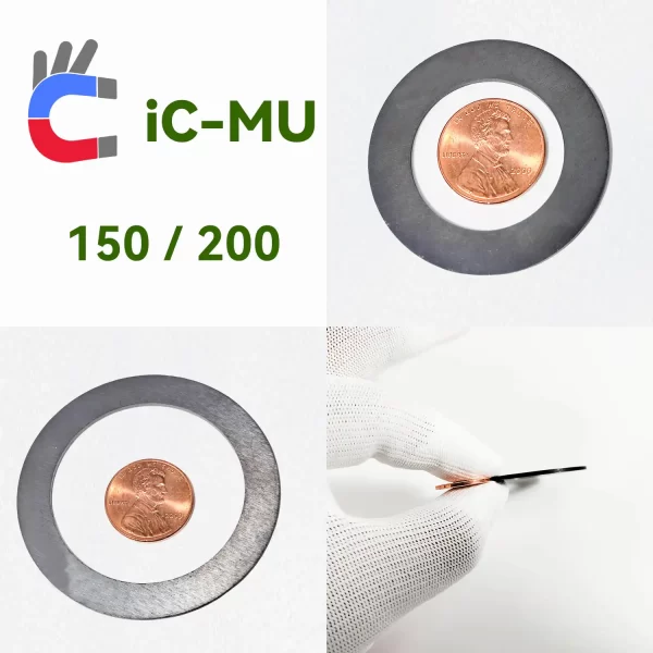
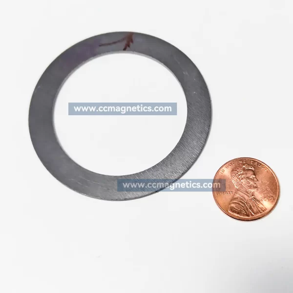
Dual-Track Encoder Ring
Ferrite Magnetic Rings for iC-MU128/150/200 Absolute Encoders
5. Master Selection Decision Matrix
The following table summarizes the trade-offs of each target architecture to assist in the initial engineering phase:
| Target Type | Shaft Compatibility | Max System Accuracy | Temp. Robustness | Relative Cost | Best Application Case | Recommended ICs |
|---|---|---|---|---|---|---|
| On-Axis Magnet | Solid Shaft Only | Medium (≈ ±0.1°) | High | Low | Compact actuators, simple brushless motors | iC-MAD, iC-TW39 |
| Off-Axis Multi-Pole | Hollow & Solid | High (≈ ±0.02°) | Medium | Medium | Robotics joints, hollow-shaft servo motors | iC-MU, iC-MUE |
| Passive Steel Gear | Hollow & Solid | High (≈ ±0.04°) | Extremely High | Low (target only) | Heavy industrial CNCs, off-highway vehicles | iC-MUE (Back-Bias) |
| Linear Magnetic Tape | Linear Guides | Medium | Medium | Low to Medium | Linear actuators, XY positioning tables | iC-MU, iC-MUE |
6. Compensation & Calibration Factor: Eccentricity Adaptation
A common engineering trap is over-specifying magnetic targets (buying ultra-precise, expensive magnetic rings) to compensate for mechanical misalignment. Modern encoder ICs make this unnecessary by solving misalignment in software.
- The Impact of Eccentricity: Physical mounting eccentricity (runout) causes severe harmonic distortion, warping the ideal sine/cosine signals into asymmetrical ellipses and introducing up to ±0.11° of angular error.
- Adaptive Gain Control (AGC): Encoder chips utilize AGC to automatically adjust internal amplification gains dynamically when the air gap fluctuates due to wobble, keeping signal amplitudes constant.
- Speed-Independent Self-Calibration: Modern encoder chips support advanced calibration routines that run even at standstill or during a simple manual back-and-forth wiggle, eliminating the need for external calibration motors.
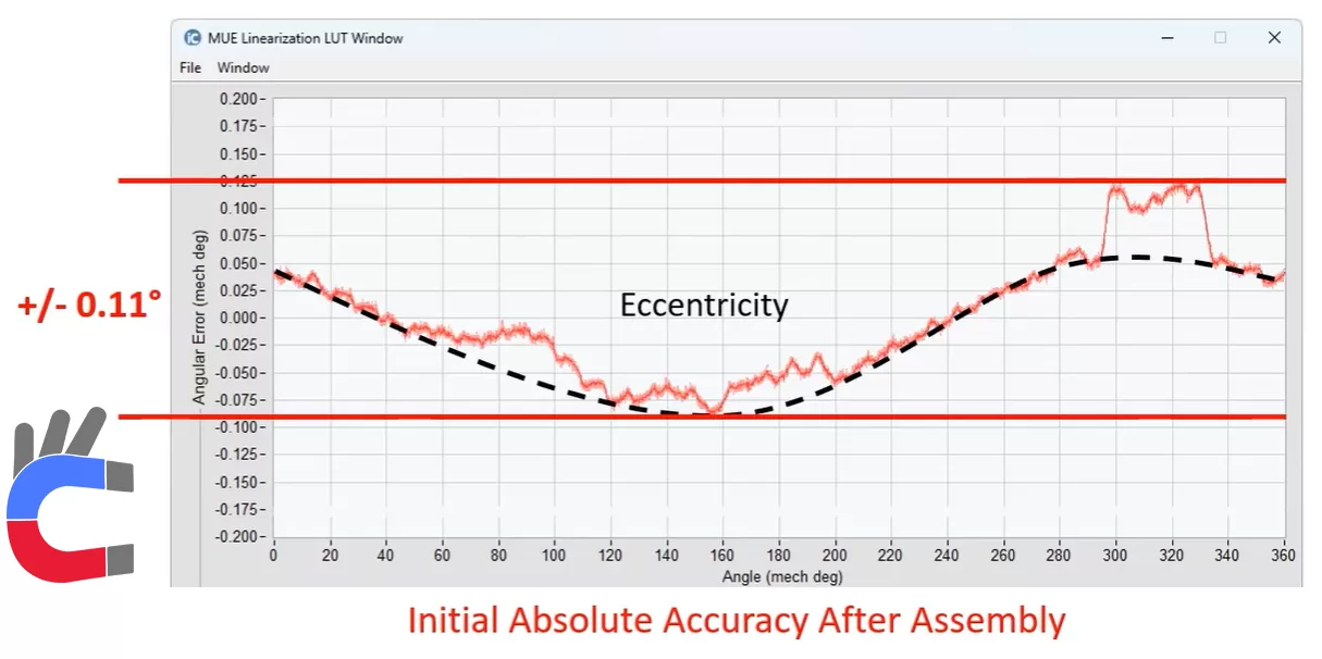
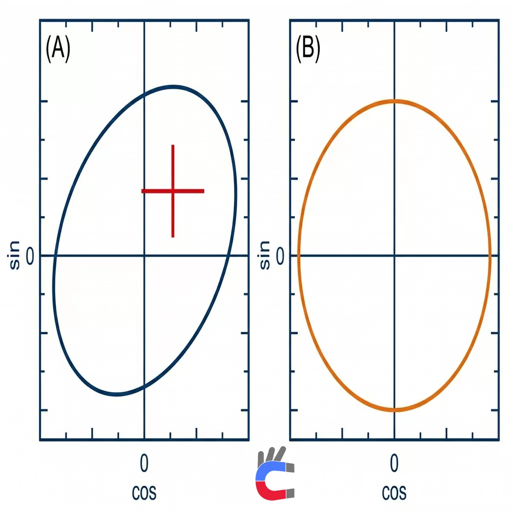
- 95% Eccentricity Compensation: Once calibrated, the chip's internal algorithms eliminate over 95% of the eccentricity-induced error, restoring distorted Lissajous signals to a perfect circle and reducing angular errors from ±0.11° down to a highly precise ±0.01° to ±0.04°.
Figure 4: Lissajous Curve Correction via On-Chip Calibration (Text-Free)
- (A) The distorted, off-center ellipse resulting from physical eccentricity before calibration.
- (B) The perfectly centered, normalized circle representing a clean angular signal after 95% eccentricity compensation.
7. Selection Checklist for Engineers
Before freezing a magnetic encoder design, system designers should verify the following parameters:
- Pole Width Matching: Ensure the target's physical pole width matches the sensor's requirements (e.g., exactly 2.0 mm for standard off-axis absolute sensors).
- Low-Power Multi-Turn Tracking: If battery-buffered multi-turn operation is required, verify that the target's pole count allows the system to remain within the ultra-low power limits (2 μA to 30 μA) of the backup tracker during power-off states.
- Thermal Expansion Rates: Account for the mismatch in thermal expansion coefficients between the metal shaft and plastic/rubber magnetic targets to prevent mechanical stress or slip at maximum RPM.
Original References & Sources
In the interest of engineering integrity and open source attribution, the technical principles detailed in this guide are sourced directly from the official iC-Haus engineering databases and technical presentations. You can watch the detailed video demonstrations below:
- Encoder Technologies & Core Transducers: iC-Haus Video u20U0B0oSq4
- Off-Axis Technology & Eccentricity Correction: iC-Haus Video J_pm7j9o8Pk
- Gear Wheel Scanning & Battery-Buffered Multi-Turn: iC-Haus Video F6YGV6LRJS8
- Vernier Nonius Calibration & Standstill Autocalibration: iC-Haus Video G8x8o-M6TM0
- Advanced Magnetic Signal Performance: iC-Haus Video QTU30N7NU8I