
 Deutsch
 Русский
 Español
 Français
 한국어
한국어 日本語
日本語
Deep Dive: Adsorption Characteristics and Obstacle-Clearing Simulation of Halbach Array Magnetic Wheels for Wall-Climbing Robots
For engineers developing non-destructive testing (NDT) wall-climbing robots, the design of the magnetic drive wheel is not only related to the payload capacity but also directly determines the movement stability and safety on complex surfaces, such as storage tanks with welds.
This post explores the design principles of Halbach array magnetic wheels based on advanced Maxwell and ADAMS simulations, and demonstrates how CCmagnetics translates these theoretical models into reliable hardware solutions.
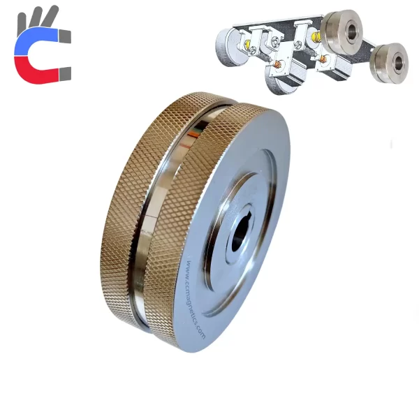
1. Magnetic Topology Comparison: Why is the Halbach Array Inevitable?
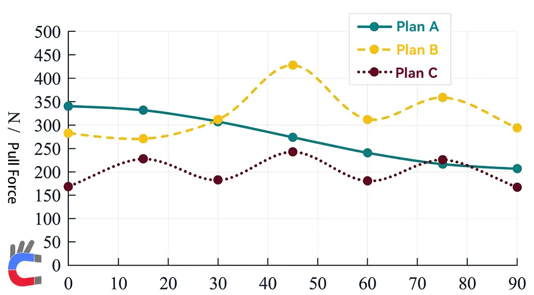
force with rotation angle
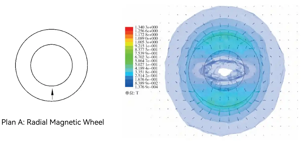
In early designs, most engineers tended to use the traditional radial magnetizing wheel (magnetic wheel 1). However, finite element analysis (FEA) using Maxwell software shows that the magnetic energy utilization of this structure is not ideal.

Magnetic Transmission
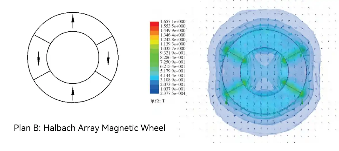
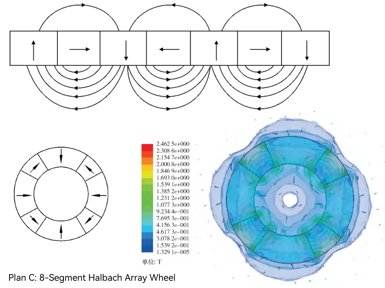
In contrast, magnetic wheels based on the Halbach array topology (magnetic wheel 2 and magnetic wheel 3) can significantly enhance the magnetic field on the adsorption side by arranging the magnetic blocks in specific directions. Specifically, the optimized "magnetic wheel 3" exhibits the most stable adsorption force as the rotation angle changes from 0° to 90°. This high degree of magnetic consistency is critical to ensuring stable motor torque output and preventing tracks from slipping during vertical climbs.
2. Magnetic Gap and Critical Safety Kinetic Models
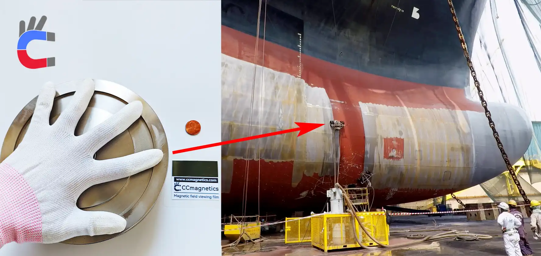
In actual applications on oil tanks or ship hulls, anti-corrosion coatings, rust, and surface roughness prevent magnetic wheels from achieving zero-distance contact with the working surface. Therefore, studying the attenuation curve of the adsorption force with the magnetic gap is crucial.
Simulation data indicates that the adsorption force of the optimized Halbach magnetic wheel reaches its maximum when the magnetic gap is 0.2 mm. More importantly for engineering guidance, as the gap increases, the descending speed of the force gradually slows down. When the working gap reaches 1.0 mm, a single wheel still has a stable adsorption force of 171 N.
In the robot body design, to prevent sliding and overturning, the total adsorption force provided by the magnetic wheels (Fm) must meet the following dynamic safety boundaries:
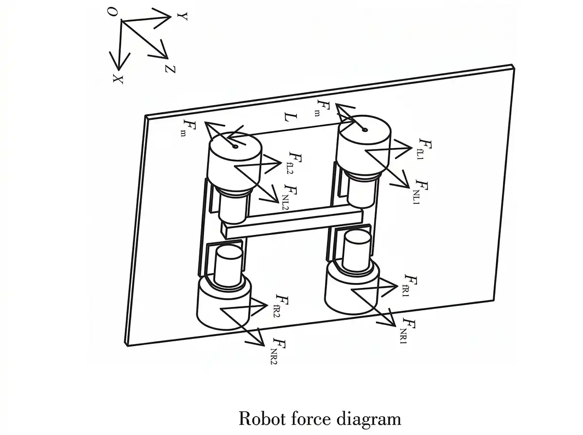
- Anti-slip condition: Fm ≥ mg / 4μ
- Anti-overturning condition: Fm ≥ mgH / 2L
For a robot with a total mass of m = 5.85 kg and a wall friction coefficient of μ = 0.2, combining the 171 N single-wheel adsorption force at a 1.0 mm gap provides immense safety redundancy. This is exactly why CCmagnetics insists on providing a detailed Pull-Test Report for every batch of magnetic wheels we deliver. We anchor these theoretical safety boundaries with empirical data, ensuring our customers have absolute confidence during system integration.
3. The Kinematic Challenge of Crossing Welds: The Necessity of Universal Magnetic Wheels
Adsorbing to flat walls is only the first step. Industrial storage tanks commonly feature circumferential and longitudinal welds with a radius of 4 mm or even 8 mm.
Kinematic simulations utilizing ADAMS software reveal a harsh reality: during the 1.5 s simulation time of climbing an 8 mm weld, the maximum offset of the mass center of the robot without a universal magnetic wheel in the X-axis direction (lateral offset) is as high as 8.13 mm due to the dual effects of gravity and magnetic field mutations. This level of deviation is detrimental